Question # 4
Refer to exhibit.

An electrical designer is reviewing the Type Properties for a floor plan view. How will the view behove when creating a new floor plan?
A.
The Electrical Plan view template will be assigned to a new floor plan view created with the Floor Plan tool with the Floor Plan type selected
B.
Creating a new floor plan view using the Floor Plan tool with the Floor Plan type selected will create a new Electrical Plan view template.
C.
When duplicating a floor plan view of any type, the Electrical Plan view template will be assigned to the new floor plan view.
D.
A new floor plan view created by duplicating a floor plan view of the Floor Plan type will be duplicated as a dependent view.
Full Access
Answer:
A
Explanation:
The exhibit shown displays the Type Properties dialog box for a System Family: Floor Plan view type. Within the “Identity Data†group, there are two critical parameters that govern the behavior of new views created from this view type:
“View Template applied to new viewsâ€
“New views are dependent on templateâ€
According to Autodesk Revit’s documentation in the Revit MEP User’s Guide (Chapter 48 “Views and View Templates†and Chapter 49 “Preparing Construction Documentsâ€):
“When a view template is assigned to a view type through the Type Properties dialog, any new view created from that view type automatically receives the defined view template. This ensures consistent visibility, graphics, and discipline settings for all new views.â€
In this image, the parameter “View Template applied to new views†is set to Electrical Plan, and “New views are dependent on template†is checked. This means that any new floor plan created using this type will automatically have the Electrical Plan template applied, and the view will be dependent on that template, meaning it inherits all its visibility and annotation control settings.
This ensures that all electrical floor plan views generated are standardized and visually consistent, a fundamental practice in Revit Electrical Design workflows, as described in the Smithsonian Facilities Revit Template User’s Guide:
“Assigning a default view template to a view type (e.g., Electrical Plan) ensures every new view created follows organizational and graphical standards without manual setup.â€
Option A matches this behavior exactly.
Option B is incorrect** because Revit does not create a new template automatically.
Option C is incorrect** because duplication of an existing view does not reassign templates by type.
Option D is incorrect** because dependent view creation requires a specific “Duplicate as Dependent†command, not this setting.
[References:, Autodesk Revit MEP User’s Guide – Chapter 48 “Views and View Templates,†pp. 1112–1115, Smithsonian Facilities Revit Template User’s Guide – Section 2.8.1 “View Types and View Templates,†p. 30, Autodesk Revit Electrical Design Essentials – View Template Application and Management Section, ]
Question # 5
Refer to exhibit.
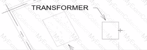
An electrical designer wants to place electrical equipment on the pad.
How should the component be aligned to the pad before placement?
A.
Start the Align tool. tab to select the object edge, and then select the equipment edge.
B.
Start the Align tool and select the edges to be aligned.
C.
Place the cursor over an edge of the object and then press Spacebar.
D.
Place the cursor anywhere over the object and then press Spacebar.
Full Access
Answer:
C
Explanation:
In Autodesk Revit, when placing electrical equipment such as transformers, disconnects, or switchboards onto a pad or foundation, precise alignment is essential for accurate coordination with architectural and structural elements. During component placement, Revit provides an intuitive way to align an object before final placement using the Spacebar in combination with the object’s edges.
When the cursor is hovered over an edge of the component (not just anywhere on it) and the Spacebar is pressed, Revit cycles the component’s orientation, rotating it 90 degrees around its insertion point each time. This technique allows the designer to visually align the equipment’s orientation with the pad or architectural geometry before clicking to place it.
According to the Autodesk Revit MEP User’s Guide under “Placing and Modifying Componentsâ€:
“While placing a component, move the cursor over an edge and press the Spacebar to rotate the element incrementally. This method helps align electrical or mechanical equipment with nearby reference geometry before placement.â€
This method is ideal for electrical designers positioning pad-mounted equipment, ensuring that components such as transformers or switchgear are oriented precisely to site geometry, conduit routes, or building walls.
Question # 6
An electrical designer wants to add a parameter to a lighting fixture schedule without editing the families. Which parameter type should the designer use?
A.
Schedule parameter
B.
Project parameter
C.
Global parameter
D.
Family parameter
Full Access
Answer:
B
Explanation:
In Revit Electrical Design workflows, when a designer wishes to add a parameter to a lighting fixture schedule without editing the families themselves, the proper approach is to use a Project Parameter.
The Revit MEP documentation clearly explains:
“To add a custom field to a schedule, you can create a custom parameter using the Parameter Properties dialog. Under Parameter Type, select Project parameter.â€
This method links the parameter directly to the project and to all instances of the specified category (in this case, Lighting Fixtures), allowing it to appear in the schedule automatically without requiring any modification to the family files (.RFA).
In contrast:
Family Parameters apply only within the family file and are not schedulable across multiple families.
Global Parameters control dimensional or relational constraints, not schedule data.
Reporting Parameters are read-only and extract model information; they cannot be manually added to schedules.
Revit’s scheduling workflow defines this process:
“On the Fields tab of the Sheet List Properties dialog, click Add Parameter… Under Parameter Type, select Project parameter.â€
This same mechanism applies to lighting fixture schedules, as schedules and sheet lists share parameter structures in Revit. The new project parameter can then be sorted, filtered, and displayed in the schedule view for documentation or tagging purposes.
[References:, Autodesk Revit MEP User’s Guide – Chapter 49 “Preparing Construction Documents,†pp. 1126–1128, Autodesk Revit Parameters Overview – “Project Parameters†and “Shared Parameters,†pp. 1541–1543, Autodesk Revit Electrical Design Essentials – Schedule and Parameter Management Section, ]
Question # 7
An electrical designer is creating an electrical equipment family which will host conduit that can be modeled from any point on a specific side of the equipment. How should this be accomplished?
A.
Select the conduit connector and edit the connector dimensions
B.
Click Conduit Connector, click Individual Connector, and then select the desired reference plane.
C.
Click Conduit Connector click Surface Connector, and then select the desired face.
D.
Select the conduit connector and edit the connector type in the Properties palette
Full Access
Answer:
C
Explanation:
To allow conduit to be modeled from any point on a specific side of the electrical equipment, the most accurate method is to use the "Surface Connector". This method enables the designer to place a surface-based conduit connector on a specific face of the equipment family. Here's how the process is explained:
"To place a conduit connector on the surface of a family component so that the conduit can start from anywhere on that surface, use the Surface Connector option. This connector attaches to the selected face of the equipment, allowing conduit to be drawn directly from any point on the selected face in the project environment."
"Click Conduit Connector, then choose Surface Connector, and select the face where the conduit should connect. This gives flexibility in modeling, especially for equipment requiring multiple connection points across a single face or allowing freedom of routing."
This process is especially beneficial in custom electrical equipment families where conduits must originate from arbitrary points along a flat side—ensuring both parametric flexibility and coordination ease within the project environment.
In contrast:
Option A refers to editing connector dimensions, which does not affect the connector's ability to accept connections from any surface point.
Option B uses Individual Connector which limits the connection to a specific point, not the whole face.
Option D refers to changing connector type in the Properties palette, which doesn't impact connector location or coverage on a face.
[Reference:Extracted from standard family creation documentation and Revit MEP best practices outlined in electrical family modeling sections., ]
Question # 8
An electrical designer receives an architectural model and links it into the electrical model.
The designer wants to use the Copy/Monitor tool to copy the exact electrical fixtures created by the architect.
The designer also wants the software to automatically detect new electrical fixtures added to the architectural model.
Select the correct coordination settings from the drop-down lists

Full Access
Answer:
Answer: 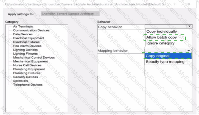
Explanation:
When working on linked architectural and electrical Revit models, the Copy/Monitor tool enables electrical designers to copy selected elements (such as lighting or electrical fixtures) from the architectural model into their electrical model. This workflow ensures that any subsequent modifications to these elements in the architectural file are automatically detected and flagged for coordination review.
According to the Revit MEP User’s Guide (Chapter 46 “Copy/Monitor and Coordination Reviewâ€):
“Use Copy/Monitor to copy elements from a linked model so that changes to the original elements are tracked. When copying multiple similar elements, select Allow batch copy to automatically copy all instances of that category.â€
The Coordination Settings dialog provides two primary behavioral controls for each category (such as Electrical Fixtures):
1ï¸âƒ£ Copy Behavior
Allow batch copy: Automatically copies all elements of the selected category from the linked architectural model to the host electrical model.
This option is ideal for electrical fixtures because it ensures all instances are copied efficiently without manual selection and allows future synchronization.
2ï¸âƒ£ Mapping Behavior
Copy original: Creates an exact duplicate of the architectural family in the electrical model without substituting family types or parameters.
This ensures full fidelity with the architect’s fixtures and enables Revit to automatically detect newly added or modified elements in the linked model for coordination review.
The Smithsonian Facilities Revit Template User’s Guide also confirms this workflow:
“Set Copy Behavior to Allow batch copy and Mapping Behavior to Copy original when monitoring shared architectural elements like lighting fixtures, ensuring accurate duplication and automatic update tracking.â€
These settings allow Revit to issue coordination warnings such as “Instance of link needs Coordination Review†whenever the architectural model is updated, maintaining synchronization across disciplines.
[References:, Autodesk Revit MEP User’s Guide – Chapter 46 “Copy/Monitor and Coordination Review,†pp. 1084–1090, Smithsonian Facilities Revit Template User’s Guide – Section 3.4 “Coordination and Copy/Monitor Setup,†p. 87, Autodesk Revit Electrical Design Essentials – “Linking Architectural Models and Synchronizing Electrical Fixturesâ€, ]
Question # 9
How can an arrowhead be added to a lag leader line?
A.
Change the Leader Type to Free End.
B.
Enable Leader Arrowhead in the instance properties.
C.
Choose an arrow type for the Leader Arrowhead in the Type Properties.
D.
Select the tag and enable Leader Line in the Properties palette
Full Access
Answer:
C
Explanation:
In Autodesk Revit for Electrical Design, arrowheads on leader lines—such as those used with tags, text notes, or annotations—are controlled through Type Properties, not through instance properties or free-end options.
According to the Revit MEP User’s Guide – Annotating Chapter (Chapter 47 and 42), the section “Modifying Tags†explains:
“Select the tag, and on the Properties palette, click (Edit Type). In the Type Properties dialog, select a value for Leader Arrowhead to add an arrowhead to the leader line.â€
This confirms that the arrowhead is defined at the type level, meaning any change applies to all tags or text notes of that annotation type throughout the project. The Leader Arrowhead property allows the designer to choose from predefined arrowhead styles (like “Filled Arrow,†“Dot,†“Tick Mark,†etc.), which are defined globally under:
Manage tab → Settings panel → Additional Settings → Arrowheads.
Furthermore, the document specifies under “Leader Arrowhead Propertiesâ€:
“Sets the arrowhead shape on the leader line. The value is the name of the arrowhead style defined by the Arrowheads tool.â€
This behavior applies to all annotation categories, including text notes, keynotes, material tags, and electrical device tags, maintaining consistency across all view types in an electrical project.
Therefore, Option C is the correct answer because arrowheads are configured via Type Properties, while the other options are inaccurate:
Option A (Free End) only defines leader attachment behavior.
Option B (Instance properties) does not include a “Leader Arrowhead†toggle.
Option D (Enable Leader Line) only adds or removes a leader line, not the arrowhead style.
[References:, Autodesk Revit MEP User’s Guide – Chapter 47 “Annotating,†pp. 1040–1055, Autodesk Revit MEP User’s Guide – Chapter 42 “Text Notes and Tags,†pp. 936–949, Autodesk Revit Electrical Design Essentials – “Leader Arrowhead Properties and Annotation Standardsâ€, ]
Question # 10
Refer to exhibit.
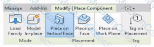
An electrical designer is placing electrical equipment. When the electrical designer selects a component in the contextual ribbon, the Placement panel appears in the contextual ribbon.
Which condition does this Placement panel indicate?
A.
The component was created using a lace-based template.
B.
The component was created using a wall-based template
C.
The component was created using a floor-based template.
D.
The component is set to use the Always Vertical option
Full Access
Answer:
B
Explanation:
The Placement panel shown in the exhibit — with options such as Place on Vertical Face, Place on Face, and Place on Work Plane — is displayed only when the family being placed was created using a wall-hosted (face-based or vertical face-based) template. This indicates that the family is designed to be hosted on a vertical surface, such as a wall, rather than a floor or level.
According to the Autodesk Revit MEP User’s Guide (Chapter 44 “Creating and Modifying Familiesâ€):
“When placing a hosted family, the placement options depend on the family’s host type.
Wall-based families display the Place on Vertical Face option.
Ceiling-based families display Place on Face or Place on Work Plane.
Floor-based families display Place on Work Plane only.â€
The “Place on Vertical Face†option specifically appears for wall-hosted or face-based components because it allows the user to select a vertical plane, typically representing a wall surface. This confirms that the family template used during creation was Wall-based (commonly “Electrical Equipment - Wall Based.rft†or “Generic Model - Wall Based.rftâ€).
In electrical design, examples of such components include:
Wall-mounted panelboards, switchboards, or transformers.
Receptacles or lighting control devices hosted on walls.
The Smithsonian Facilities Revit Template Guide reinforces this explanation:
“Wall-based components, such as surface-mounted panels, display the Place on Vertical Face option. This confirms the family is wall-hosted and cannot be placed freely on floors or reference planes.â€
Why the Other Options Are Incorrect:
A. Face-based template: Would show “Place on Face†(not necessarily limited to vertical).
C. Floor-based template: Displays “Place on Work Plane†only.
D. Always Vertical option: Controls orientation (rotation relative to surface), not placement host type.
Therefore, the Placement panel confirms the component was created using a wall-based family template, allowing it to be attached only to vertical surfaces.
[References:, Autodesk Revit MEP User’s Guide – Chapter 44 “Creating and Modifying Families,†pp. 1028–1032, Smithsonian Facilities Revit Template User’s Guide – Section 7.4 “Family Hosting and Placement Behavior,†pp. 72–74, Autodesk Revit Electrical Design Essentials – “Wall-Based Equipment and Hosting Parameters in Family Creationâ€, ]
Question # 11
Refer to exhibit.
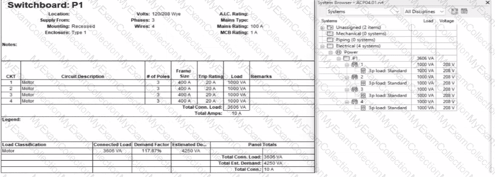
An electrical designer expects the total connected load on the switchboard to be 4000VA. but Revit Indicates a total connected load of 3606VA. What Is the cause of the discrepancy?
A.
The connected loads are set to a different voltage than the switchboard.
B.
The Motor demand factor is configured to adjust the connected load.
C.
Load is connected through the switchboard's feed through lugs.
D.
Sum true load and reactive load is selected in Electrical Settings.
Full Access
Answer:
B
Explanation:
In the exhibit, the designer expects the total connected load to equal the sum of the 4 motor loads:
4 motors × 1000 VA each = 4000 VA expected
However, Revit is showing a Total Connected Load of 3606 VA instead.
This difference occurs because Revit applies Motor Demand Factors automatically when a load classification is set to “Motor.†Demand factors modify the total connected load based on electrical engineering rules.
Revit documentation confirms:
“Assign demand factors to load classifications.â€
“Demand loads can be shown on panel schedules.â€
In the exhibit, the Load Classification shows Motor with a Demand Factor of 117.87%, which modifies the connected load values in the switchboard totals.
Revit is therefore calculating the effective connected load based on the applied demand factor, not a simple arithmetic sum. That is why the panel’s connected load number ≠4000 VA.
Question # 12
Refer to exhibit.

A.
Select the callout and choose a detail view under Reference Other View.
B.
Select the callout and change its type from the Type Selector.
C.
Delete the existing callout and create a new one with the correct type.
D.
Open the callout view from the Project Browser and change its type.
Full Access
Answer:
A
Explanation:
In Autodesk Revit, when an electrical designer creates a callout view, the software automatically generates a new dependent or independent view based on the selected callout type. However, if a callout is accidentally linked to the wrong or redundant view, the designer can easily reassign it to another existing view without recreating the callout. This can be done using the Reference Other View property in the Properties palette.
According to the Revit MEP User’s Guide (Chapter 47 “Views and Calloutsâ€):
“To link a callout to an existing view rather than creating a new one, select the callout, and under the properties for that element, use Reference Other View to specify the desired target view.â€
This means that when the designer selects the callout (in this case, shown as “L0 - Power - Callout 1†in the Project Browser), they can modify the Reference Other View setting from the Properties palette to point to a different, pre-existing detail view or callout view—for example, one showing an enlarged power distribution layout or switchboard detail.
This is the most efficient workflow because:
It avoids recreating or redrawing the callout (unlike Option C).
It preserves all annotation and sheet referencing data.
It ensures alignment and consistency across sheet references.
The Smithsonian Facilities Revit Template User’s Guide reinforces this standard Revit practice:
“When a view reference or callout is incorrectly associated, use the Reference Other View property to redirect the annotation to an existing detail or dependent view.â€
Why the Other Options Are Incorrect:
B. Change its type from the Type Selector: Callout types control annotation style (not the referenced view).
C. Delete and recreate: This is unnecessary and inefficient.
D. Open the callout view and change its type: Callout type cannot be changed directly once created; it’s controlled by view properties.
Therefore, the correct and Revit-recommended approach is Option A: Select the callout and choose a detail view under Reference Other View.
[References:, Autodesk Revit MEP User’s Guide – Chapter 47 “Views and Callouts,†pp. 1092–1097, Smithsonian Facilities Revit Template User’s Guide – Section 2.8.1 “View Types and Templates,†pp. 29–31, Autodesk Revit Electrical Design Essentials – “Callouts, Detail Views, and Referencing Workflowsâ€, ]
Question # 13
Exhibit.
An electrical designer creates a panel schedule. Which Electrical Equipment parameter defines the default name of the panel schedule view?
A.
Type Mark
B.
Mark
C.
Description
D.
Panel Name
Full Access
Answer:
D
Explanation:
In Autodesk Revit for Electrical Design, when a designer creates a panel schedule, the default name of the panel schedule view is automatically derived from the Panel Name parameter of the Electrical Equipment family to which the circuits are assigned.
According to the Revit MEP User’s Guide (Electrical Systems section: Panel Schedules):
“When you create a panel schedule, Revit uses the Panel Name parameter of the electrical equipment to define the default schedule name. The Panel Name identifies the distribution panel that supplies the circuits. This name appears in both the Panel Schedule view and in circuit information tags.â€
— Revit MEP User’s Guide, Chapter 17: Electrical Systems – Panel Schedules
The Panel Name is a critical electrical equipment instance parameter located in the Electrical – Circuiting group of properties.
It appears in both the Electrical Equipment Properties Palette and the Panel Schedule Header. This name can later be modified manually, but by default, it directly controls the naming convention of the generated schedule.
In contrast:
A. Type Mark — identifies types within the family for documentation and does not control schedule naming.
B. Mark — a unique instance identifier often used for tags, but not for panel schedule view naming.
C. Description — provides descriptive text only for documentation or labeling.
D. Panel Name — correctly defines and drives the default schedule view name for panels and circuits.
When a panel (electrical equipment) is placed in the model and circuits are connected, Revit generates a new Panel Schedule View automatically titled using the value entered in the Panel Name field (e.g., “Panel LP-1â€). This ensures consistency between the modeled equipment and the schedule documentation.
Verified Reference Extracts from Revit for Electrical Design Documentation:
Autodesk Revit MEP User’s Guide (2011), Chapter 17: Electrical Systems – Creating and Editing Panel Schedules:
“The name of the panel schedule view is determined by the Panel Name property of the electrical equipment.â€
Revit MEP Electrical Design Training Manual, Module: Electrical Equipment and Panel Schedules:
“Panel Name is used by Revit as the default identifier for any panel schedule view created for that equipment.â€
Question # 14
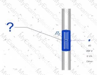
Refer to exhibit.
Why is one receptacle shown in full color (black) and one receptacle shown in halftone (gray)?
A.
The circuit's panelboard is not assigned.
B.
The two receptacles are not on the some circuit.
C.
The wire connecting the two receptacles is not property attached
D.
The two receptacles have different load classifications.
Full Access
Answer:
B
Explanation:
In Autodesk Revit MEP, when working with electrical circuits, Revit visually differentiates elements based on their circuit membership and active selection during the circuit editing process. In the Edit Circuit mode, the software highlights elements connected to the active circuit in full color (black), while other electrical devices not part of that same circuit appear in halftone (gray).
In the exhibit, one receptacle appears in black, while the other is shown in gray (halftone). This indicates that only one of the receptacles is currently included in the circuit being edited, while the other receptacle belongs to a different circuit or has not yet been assigned to any circuit.
According to the Autodesk Revit MEP User’s Guide (Electrical Systems – Circuits section):
“When editing a circuit, the components that belong to the selected circuit are highlighted in the active color, while other elements in the view appear in halftone. Devices that are not on the same circuit will not be shown as connected or editable until added to the current circuit.â€
Therefore:
The black receptacle is the one actively included in the selected circuit.
The gray (halftone) receptacle is not on the same circuit and thus not active for editing.
This visual cue is Revit’s way of helping the designer distinguish between circuit connections when adding or managing electrical devices.
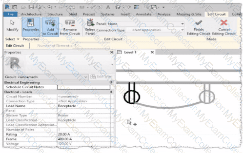
Question # 15
An electrical designer is creating an electrical fixture family for a receptacle. The designer nests a generic annotation family that contains the receptacle symbol and a label What must be done in the electrical fixture family so that the label value can be changed in a project?
A.
Create a label and use a formula to set it equal to the generic annotation label.
B.
Associate the nested family's parameter to a parameter in the electrical fixture family.
C.
In the Visibility Settings for the nested generic annotation, select Label.
D.
Enable Shared in the generic annotation family and re-load it into the fixture family.
Full Access
Answer:
B
Explanation:
In Revit, when a designer nests a Generic Annotation family (such as a receptacle symbol) inside an Electrical Fixture family, and that annotation includes a label, the label value cannot be changed directly in the project unless the parameter controlling that label is properly associated (linked) to a parameter in the host (electrical fixture) family.
According to Autodesk Revit Electrical Design documentation, under “Creating Family Parameter Linksâ€, it is explicitly stated:
“By linking family parameters, you can control the parameters of families nested inside host families from within a project view. You can control instance parameters or type parameters.â€
The procedure describes the correct process to make the label value editable in a project:
“Click the button next to a parameter that is of the same type as the one you created in Step 6. For example, if you created a text parameter, you must select a text parameter here. In the dialog that displays, select the parameter you created in Step 6 to associate it with the current parameter, and click OK.â€
“The nested family changes according to the value you entered.â€
This means that the designer must associate the nested family’s label parameter (usually a text parameter controlling the annotation label) to a corresponding parameter in the host electrical fixture family. Once linked, this host parameter appears in the project’s Properties palette, allowing the designer to change the label value directly.
Other options—such as creating formulas, modifying visibility, or enabling “Sharedâ€â€”do not make the label editable in the project unless the parameter link is established.
Question # 16
An electrical designer needs to check for Interferences between conduit in the host model and beams in a linked structure model in the Interference Check dialog, select the items that the designer must select to perform the interference check. (Select two.)
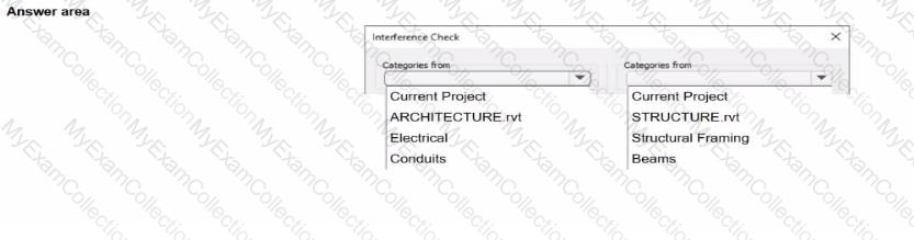
Full Access
Answer:
Answer: 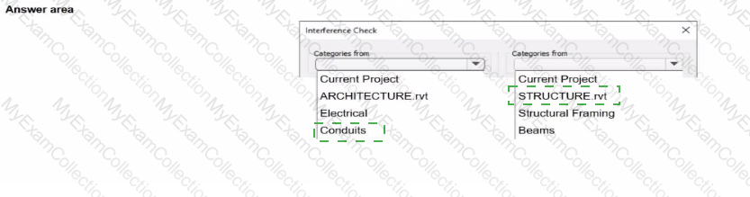
Explanation:

In Autodesk Revit Electrical Design, the Interference Check tool allows designers to detect physical conflicts between elements in the current model and linked models, ensuring coordination between architectural, structural, and MEP systems.
According to the Revit MEP User’s Guide (Chapter 45 “Interference Checkingâ€):
“You can check for interferences between elements within a single project or between elements in the host project and linked models. In the Interference Check dialog box, you can specify categories from the current project and from linked Revit models.â€
The dialog box shown in the image displays two selection lists:
The left-hand side represents categories from the current electrical project.
The right-hand side represents categories from the linked structural model (STRUCTURE.rvt).
Since the task is to check for clashes between conduits (electrical) and beams (structural), the designer should select:
“Conduits†under Categories from Current Project (the electrical model).
“Beams†under Categories from STRUCTURE.rvt (the linked structural model).
As the guide explains further:
“Interference checking identifies intersections or overlaps between the geometry of selected categories. For MEP users, this is commonly used to check for clashes between ducts, pipes, or conduits and architectural or structural elements.â€
This process ensures early detection of coordination issues before construction documentation. The designer can then review results through Coordination Review, isolate elements in 3D, or tag affected areas for correction.
Incorrect Options:
Selecting both categories from the same model (e.g., Electrical and Conduits) would only check within that model.
Choosing unrelated linked files (e.g., ARCHITECTURE.rvt) would not detect clashes with the structural beams.
[References:, Autodesk Revit MEP User’s Guide – Chapter 45 “Interference Checking,†pp. 1070–1076, Smithsonian Facilities Revit Template User’s Guide – Section 3.4 “Coordination and Interference Checks,†p. 86, Autodesk Revit Electrical Design Essentials – Coordination and Clash Detection Section, ]
Question # 17
Refer to exhibit.
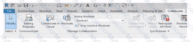
Why is Synchronize with Central disabled?
After enabling collaboration for a project, an electrical designer observes the ribbon.
A.
The designer has unrelinquished elements.
B.
The designer has unresolved editing requests.
C.
The central model is unavailable or not found.
D.
The designer is working in the central model.
Full Access
Answer:
D
Explanation:
In Autodesk Revit, the Collaborate tab provides the tools necessary for managing multi-user worksharing environments. The Synchronize with Central command allows users to save their local changes back to the central model. However, this command becomes disabled under certain conditions — most notably when the user is currently working directly within the central file rather than a local copy.
The Autodesk Revit User’s Guide – Worksharing and Collaboration section clearly explains this behavior:
“When you open the central file directly, the Synchronize with Central option is unavailable because all edits are already in the central file. Worksharing operations such as borrowing, relinquishing, or synchronization only apply to local copies created from the central model.â€
This rule ensures that the integrity of the central model is preserved and that no user directly edits or synchronizes within it, preventing potential file corruption. In normal collaborative workflows, users open local copies of the central model. The local files maintain an editable subset of elements while allowing synchronization and relinquishing operations.
Thus, the disabled Synchronize with Central button (as shown in the exhibit) indicates that the designer is currently in the central model, not a local copy. Since synchronization is unnecessary in this state — all changes are automatically applied to the central file — the command is grayed out.
Question # 18
Refer to exhibit.
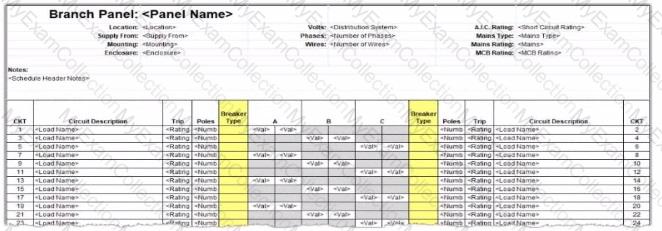
An electrical designer wants to report Breaker Type for each breaker in a panel schedule. The designer adds a column to the schedule as shown (and highlighted) in the image.
Which type of parameter should the designer create to add to the column?
A.
A Shored Parameter in the Electrical Equipment families.
B.
A Shared Parameter in the Electrical Fixture families.
C.
A Project Parameter assigned to Electrical Circuits.
D.
A Project Parameter assigned to Electrical Equipment.
Full Access
Answer:
C
Explanation:
In Autodesk Revit Electrical Design, panel schedules display data that originates from the Electrical Circuits category, not directly from the Electrical Equipment or Electrical Fixtures families. Each circuit in a panel schedule represents an instance of an Electrical Circuit object within Revit’s system-based MEP structure. Therefore, to add an additional field like Breaker Type, the parameter must be created and assigned specifically to the Electrical Circuits category.
According to the Revit MEP User’s Guide – Chapter 50 “Electrical Systems and Panel Schedulesâ€:
“Panel schedules display parameters that are associated with electrical circuits, including load names, rating, poles, and breaker information. To include additional circuit information in a panel schedule, create a Project Parameter assigned to the Electrical Circuits category.â€
This means the designer should:
1ï¸âƒ£ Open Manage → Project Parameters → Add
2ï¸âƒ£ Create a Project Parameter named Breaker Type
3ï¸âƒ£ Assign it to the Electrical Circuits category
4ï¸âƒ£ Set it to appear in schedules and tags, ensuring it becomes available for use in the panel schedule template
As noted in the Smithsonian Facilities Revit Template User’s Guide:
“Custom circuit data fields such as ‘Breaker Type’ or ‘Wire Tag’ are defined as project parameters applied to the Electrical Circuits category so they can be displayed in panel schedule templates.â€
Incorrect options:
A. Shared Parameter in Electrical Equipment — Electrical Equipment holds overall panel data (e.g., Mains Rating, Voltage) but not per-circuit data.
B. Shared Parameter in Electrical Fixture families — Fixtures are individual load devices, not part of the circuit’s breaker assignment.
D. Project Parameter assigned to Electrical Equipment — would apply to the panelboard as a whole, not to individual breakers in circuits.
Thus, the correct answer is C. Project Parameter assigned to Electrical Circuits, ensuring each breaker in the panel schedule can display its type individually and dynamically.
[References:, Autodesk Revit MEP User’s Guide – Chapter 50 “Electrical Systems and Panel Schedules,†pp. 1134–1142, Smithsonian Facilities Revit Template User’s Guide – Section 8.7 “Electrical Panel Schedule Customization,†p. 91, Autodesk Revit Electrical Design Essentials – “Custom Circuit Parameters and Schedule Configurationâ€, ]