Question # 4
Which mechanism allows WPA3 to provide a higher degree of security than its predecessors?
Question # 5
Which AP mode wirelesssly connects two separate network segments each set up within a different campus building?
Question # 8
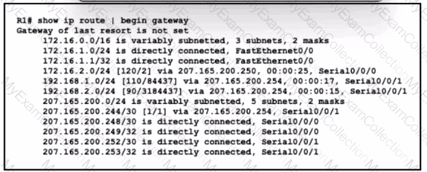
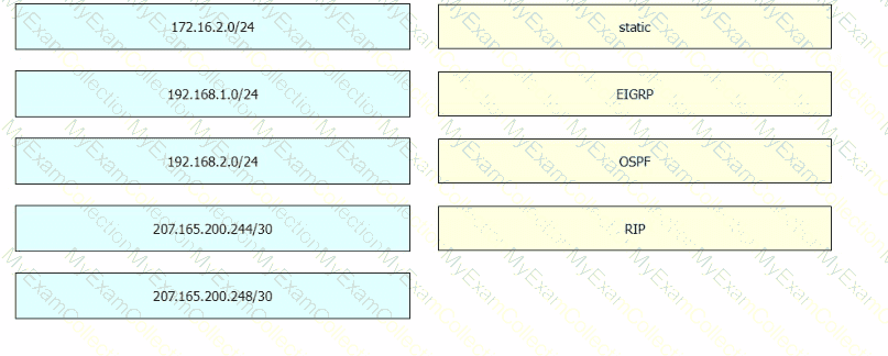
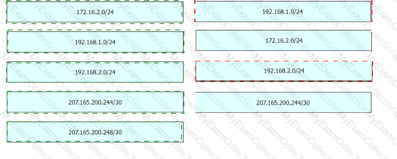
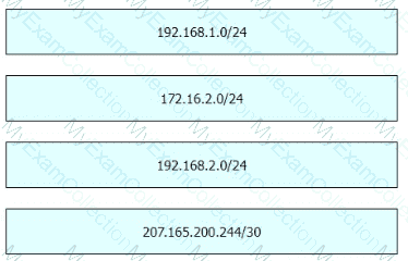
Refer to the exhibit. Drag and drop the learned prefixes from the left onto the preferred route methods from which they were learned on the right.
Question # 9
What is the default interface for in-band wirelesss network management on a WLC?
Question # 10
Refer to the exhibit.
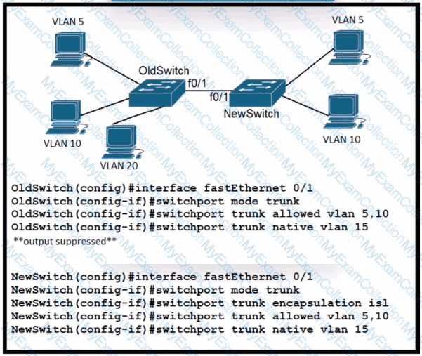
A new VLAN and switch are added to the network. A remote engineer configures OldSwitch and must ensure that the configuration meets these requirements:
• accommodates current configured VLANs
• expands the range to include VLAN 20
• allows for IEEE standard support for virtual LANs
Which configuration on the NewSwitch side of the link meets these requirements?
A)

B)
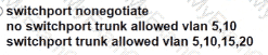
C)

D)

Question # 11
Which technology allows multiple operating systems lo run a single physical server?
Question # 13
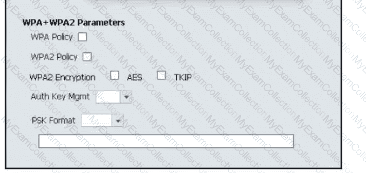
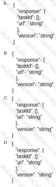
Refer to the exhibit.
Which configuration is needed to configure a WLAN with WPA2 only and with a password that is 63 characters long?
Question # 14
Which technology is appropriate for communication between an SDN controller and applications running over the network?
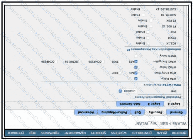
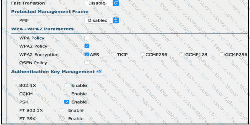
Question # 15
Refer to the exhibit. An engineer is using the Cisco WLC GUI to configure a WLAN for WPA2 encryption with AES and pre-shared key Cisc0123456. After the engineer selects the WPA + WPA2 option froin the Layer 2 Security drop-down list, which two tasks must they perform to complete the process? (Choose two.)
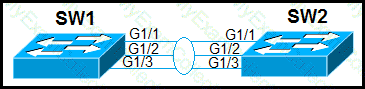
Question # 16
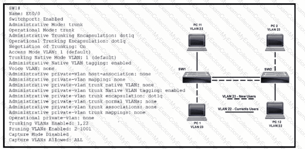
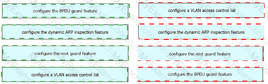
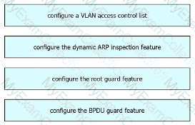
Refer to the exhibit. VLAN 23 is being implemented between SW1 and SW2. The command show interface ethernet0/0 switchport has been issued on SW1. Ethernet0/0 on SW1 is the uplink to SW2. Which command when entered on the uplink interface allows PC 1 and PC 2 to communicate without impact to the communication between PC 11 and PC 12?
Question # 17
Refer to the exhibit.
Packets are flowing from 192.168.10.1 to the destination at IP addressss 192.168.20.75. Which next hop will the router select for the packet?
Question # 18
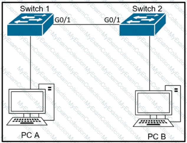
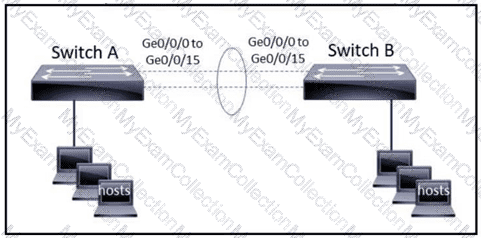
Refer to the exhibit.
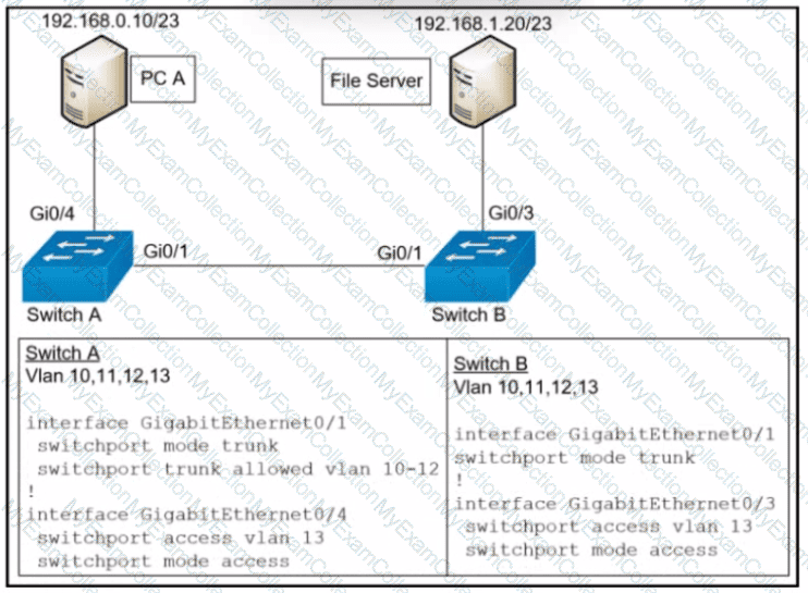
PC A and the file server. Which command must be configured on switch A to prevent interruption of other communications?
Question # 20
Which mechanism carries multicast traffic between remote sites and supports encryption?
Question # 21
Which set of actions satisfies the requirement for multifactor authentication?
Question # 22
Which type of hypervisor operates without an underlying OS to host virtual machines?
Question # 24
How does a network administrator securely manage an AP in lightweight mode?


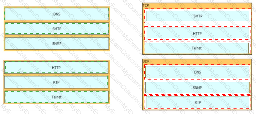
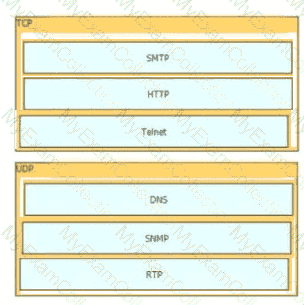
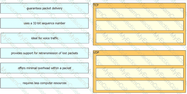
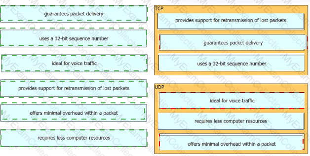
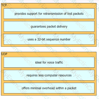
Question # 26
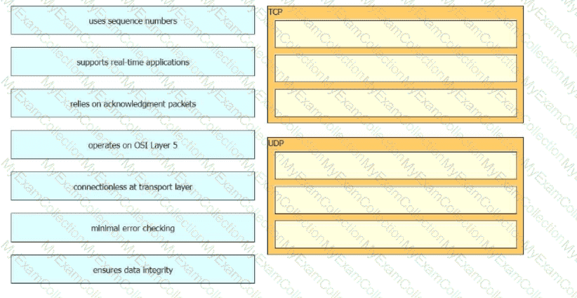
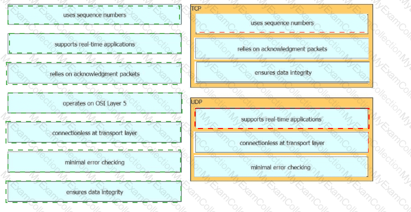
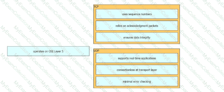
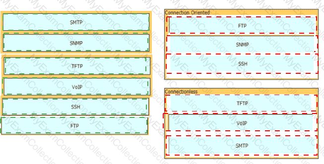
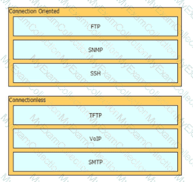
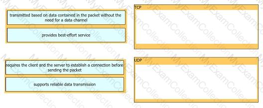
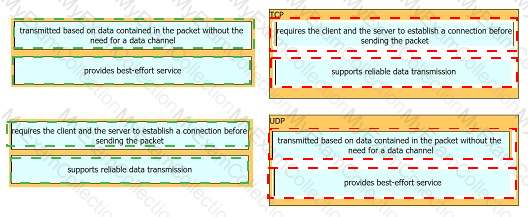
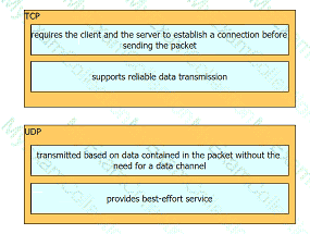
Drag and drop the TCP and UDP characteristics froin the left onto the supporting protocols on the right. Not all options are used.
Question # 27
Which two northbound APIs are found in a software-defined network? (Choose two.)
Question # 30
Exhibit.

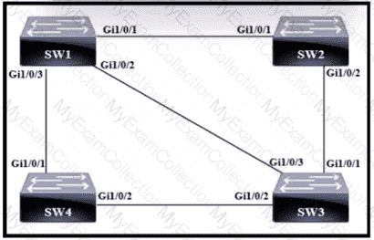
The switches are connected via a Cat5 Ethernet cable that was successfully tested. The Interfaces are configured as access ports and are both in a ' down " status. What is the cause of this issue?
Question # 31
Refer to the exhibit. Which functionalities will this SSID have while being used by wirelesss clients?
Question # 32
What is the temporary state that switch ports always enter immediately after the boot process when Rapid PVST+ is used?
Question # 34
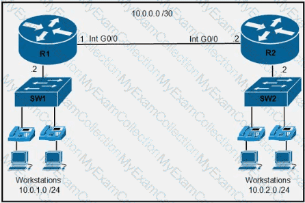
A network engineer must configure the router R1 GigabitEthernet1/1 interface to connect to the router R2 GigabitEthernet1/1 interface. For the configuration to be applied, the engineer must compress the addresss 2001:0db8:0000:0000:0500:000a:400F:583B. Which command must be issued on the interface?
Question # 35
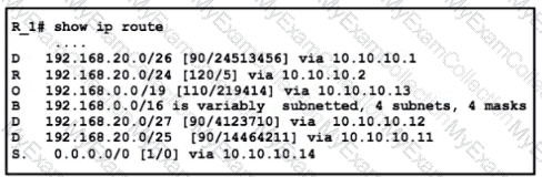
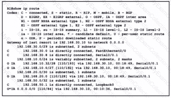
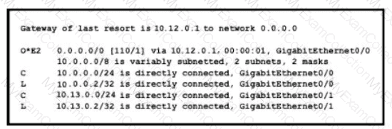
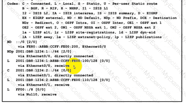
Refer to the exhibit. What is the administrative distance for the advertised prefix that includes the host IP addressss 192.168.20.1?
Question # 36

Refer to the exhibit Routers R1 R2 and R3 use a protocol to identify their neighbors ' IP addresssses hardware platforms, and software versions. A network engineer must configure R2 to avoid sharing any neighbor information with R3, and maintain its relationship with R1. What action meets this requirement?
Question # 41
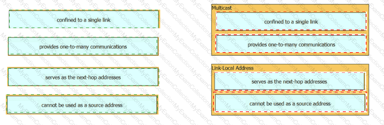
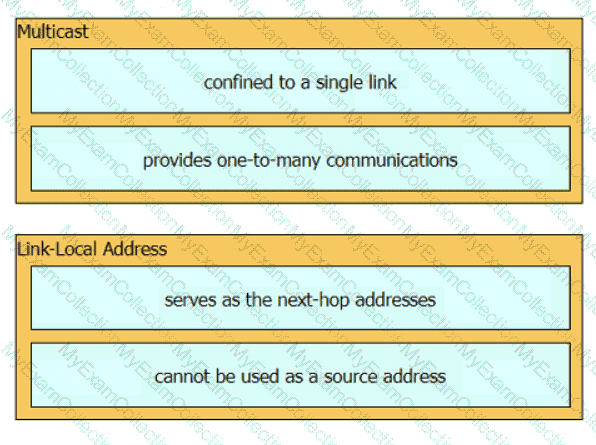
Drag and drop the characteristic from the left onto the IPv6 address type on the right.

Question # 42
How does IPsec provide secure networking for applications within an organization?
Question # 43
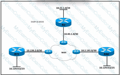
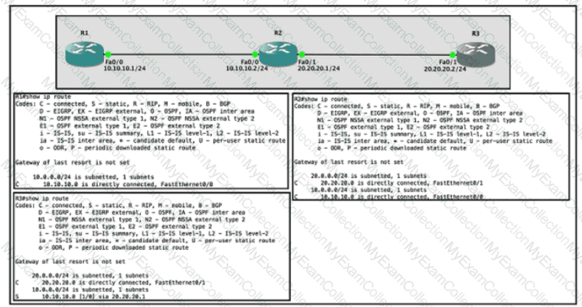
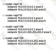
Refer to the exhibit. All routers in the network are configured conrectly, and the expected routes are being exchanged among the routers. Which set of routes are leamed from neighbors and installed on router 2?
Question # 44
A DHCP pool has been created with the name NOCC. The pool is using 192.168.20.0/24 and must use the next to last usable IIP address as the default gateway for the DHCP clients. What is the next step in the process?
Question # 45
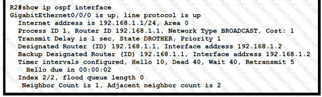
Refer to the exhibit.
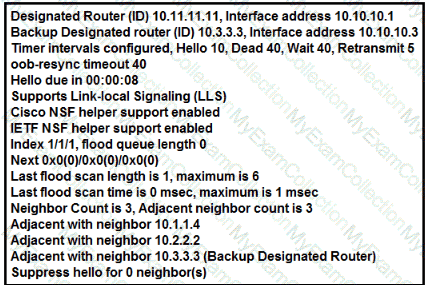
The show ip ospf interface command has been executed on R1. How is OSPF configured?
Question # 46
Refer to the exhibit.
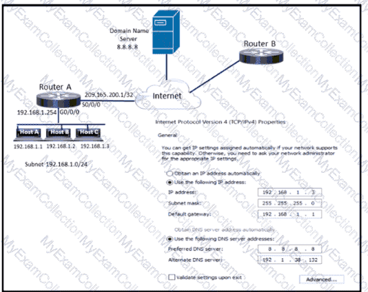
Which configuration parameter is preventing host C from reaching the internet?
Question # 48
Refer to the exhibit.
Which interface is chosen to forward traffic to the host at 192.168.0.55?
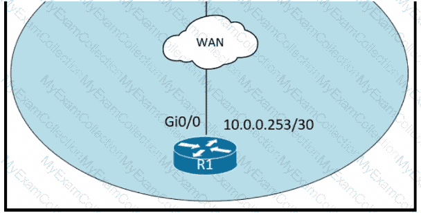
Question # 49
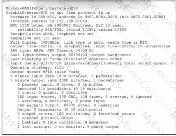
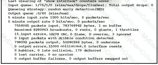
Refer to the exhibit. Router-WAN1 has a new connection via Gi0/0 to the ISP. Users running the web applications indicate that connectivity is unstable to the internet. What is causing the interface issue?
Question # 50
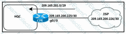
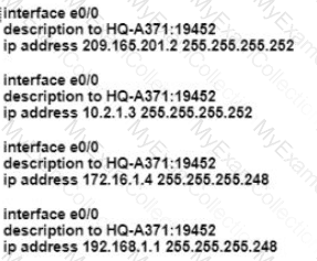
Refer to the exhibit. HQC needs to use a configuration that:
handles up to 150,000 concurrent connections
minimizes consumption of public IP addresssses
Question # 51
Which type of DNS record is used to specify the mail server responsible for accepting email messages on behalf of a recipient ' s domain?
Question # 52
An on-site service desk technician must verify the IP addressss and DNS server information on a users Windows computer. Which command must the technician enter at the command prompt on the user ' s computer?
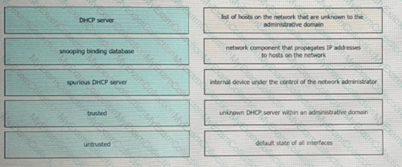
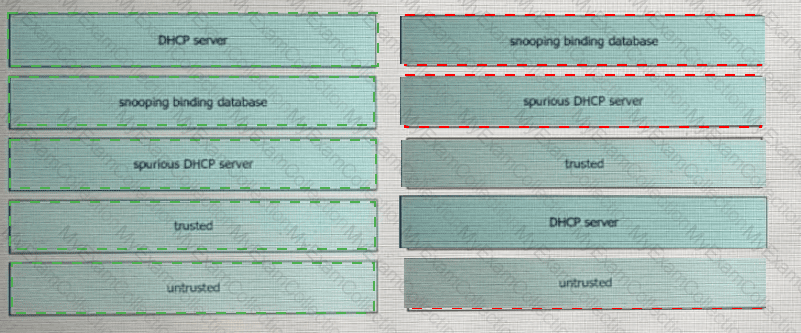
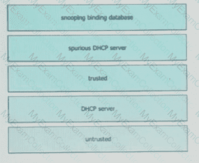
Question # 53
Drag and drop the DHCP snooping terms from the left onto the descriptions on the right.
Question # 54
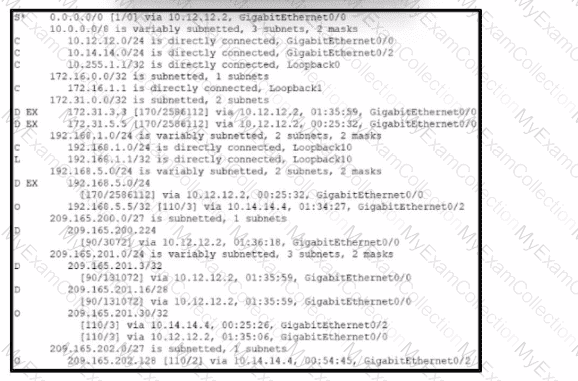
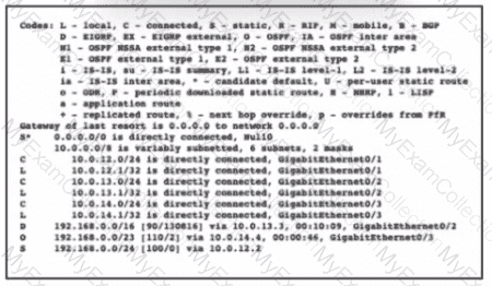
Refer to the exhibit. Four load-balancing servers are reachable through this router; however, the company is removing all static and default routes on the router.
Server 1 - 10.12.14.14
Server 2 - 192.168.4.4
Server 3 - 209.165.200.5
Server 4 - 209.165.201.26
Which server will handle all traffic after the policy changes take effect?
Question # 55
Refer to the exhibit.
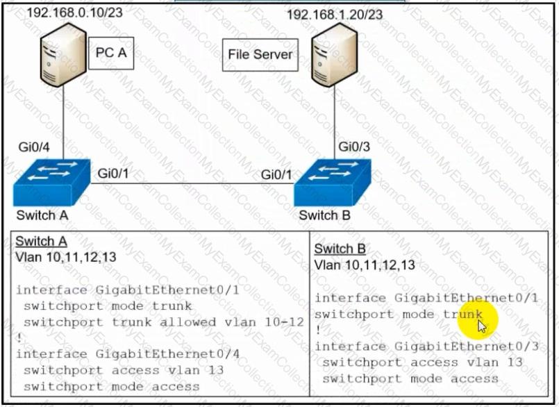
A network engineer must configure communication between PC A and the File Server. To prevent interruption for any other communications, which command must be configured?
Question # 56
By default, how does EIGRP determine the metric of a route for the routing table?
Question # 57
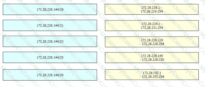
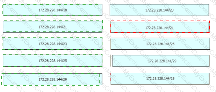
Drag and drop the IPv4 network subnets from the left onto the correct usable host ranges on the right

Question # 58
Refer to the exhibit.
Router OldR is replacing another router on the network with the intention of having OldR and R2 exchange routes_ After the engineer applied the initial OSPF
configuration: the routes were still missing on both devices. Which command sequence must be issued before the clear IP ospf process command is entered to enable the neighbor relationship?
Question # 59
An email user has been lured into clicking a link in an email sent by their company ' s security organization. The webpage that opens reports that it was safe but the link could have contained malicious code. Which type of security program is in place?
Question # 60
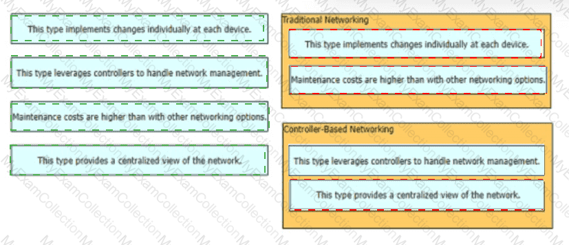
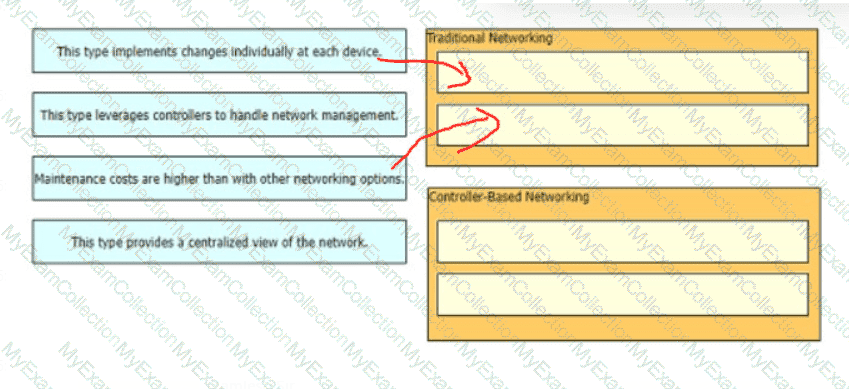
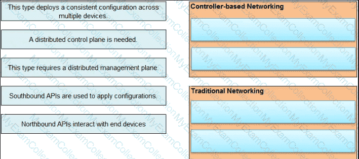
What are two benefits of controller-based networking compared to traditional networking?
Question # 61
What is the purpose of using First Hop Redundancy Protocol in a specific subnet?
Question # 62
Which implementation provides the strongest encryption combination for the wireless environment?
Question # 64
When DHCP is configured on a router, which command must be entered so the default gateway is automatically distributed?
Question # 65
When implementing a router as a DHCP server, which two features must be configured ' ? (Choose two)
Question # 66
Which two command sequences must you configure on switch to establish a Layer 3 EtherChannel with an open-standard protocol? (Choose two)
Question # 67
Refer to the exhibit.
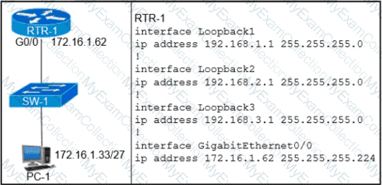
Which configuration on RTR-1 denies SSH access from PC-1 to any RTR-1 interface and allows all other traffic?
Question # 68
Which two protocols are supported on service-port interfaces? (Choose two.)
Question # 69
What are two roles of the Dynamic Host Configuration Protocol (DHCP)? (Choose two)
Question # 71
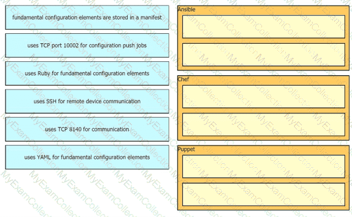
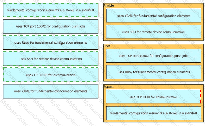
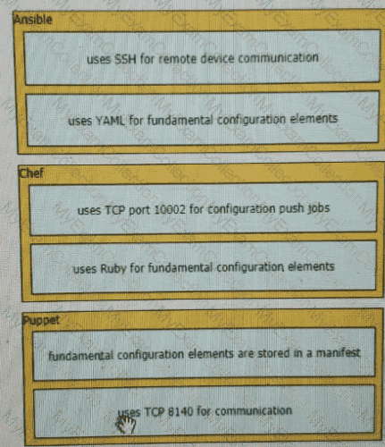
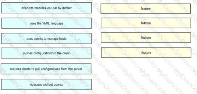
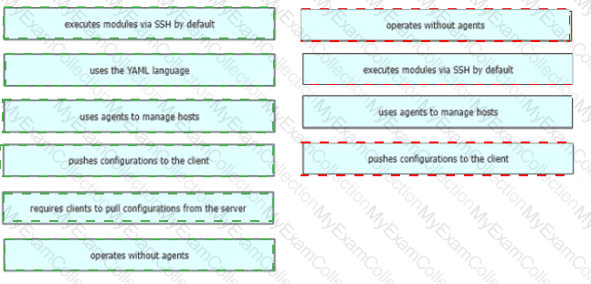
Drag and drop the descriptions from the left onto the correct configuration-management technologies on the right.
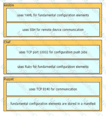
Question # 72
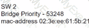
Refer to the exhibit.
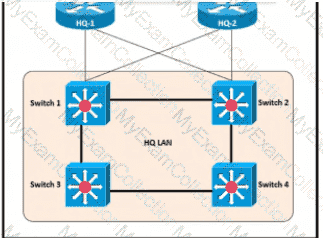
After the election process what is the root bridge in the HQ LAN?

Question # 74
Refer to the exhibit.
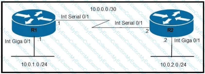
An administrator must turn off the Cisco Discovery Protocol on the port configured with address last usable address in the 10.0.0.0/30 subnet. Which command set meets the requirement?
Question # 75
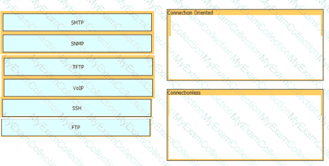
Drag and drop the network protocols from the left onto the correct transport services on the right.
Question # 76
An engineer must configure a /30 subnet between two routers. Which usable IP address and subnet mask combination meets this criteria?
Question # 78
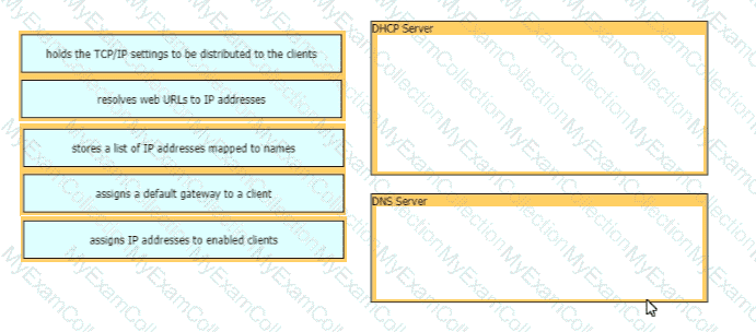
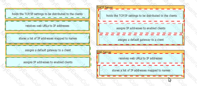
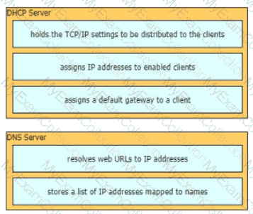
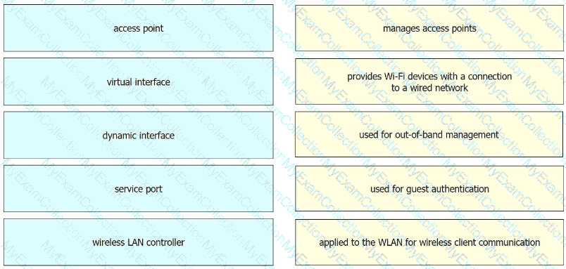
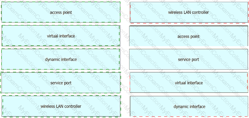
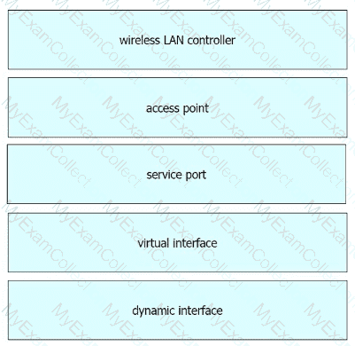
Drag and drop the functions from the left onto the correct network components on the right
Question # 80
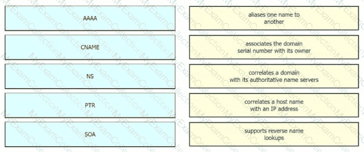
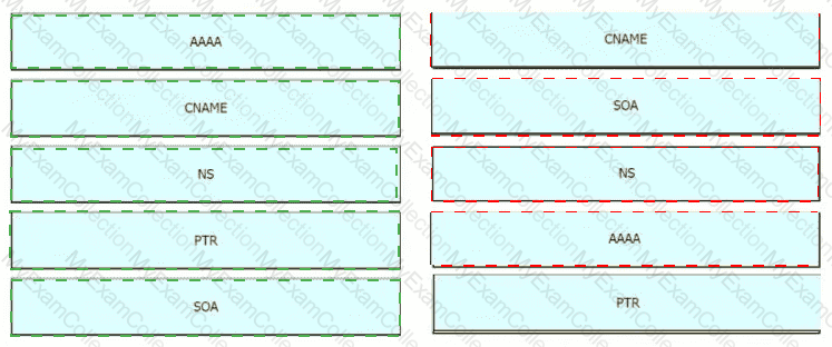
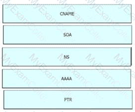
Drag the IPv6 DNS record types from the left onto the description on the right.
Question # 82
In software-defined architectures, which plane is distributed and responsible for traffic forwarding?
Question # 83
Which device tracks the state of active connections in order to make a decision to forward a packet through?
Question # 84
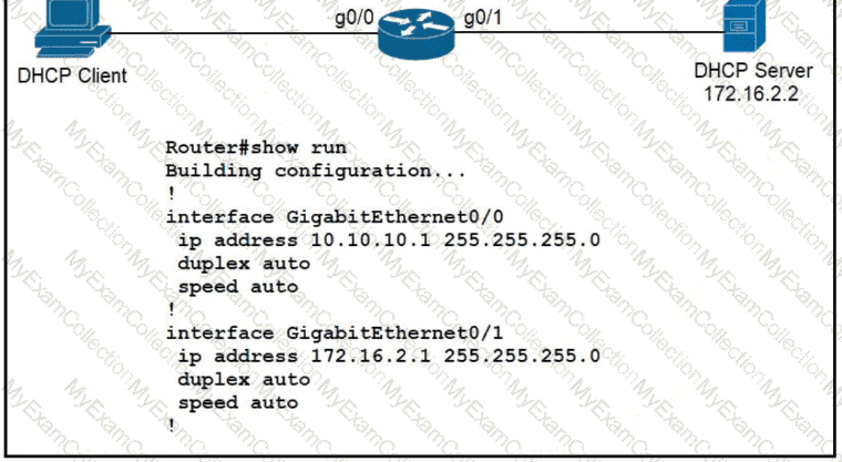
A network administrator must enable DHCP services between two sites. What must be configured for the router to pass DHCPDISCOVER messages on to the server?
Question # 85
What is an advantage of Cisco DNA Center versus traditional campus device management?
Question # 86
What uses HTTP messages to transfer data to applications residing on different hosts?
Question # 87
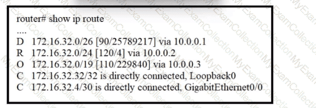
Refer to the exhibit.
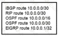
A router received these five routes from different routing information sources.
Which two routes does the router install in its routing table? (Choose two)
Question # 88
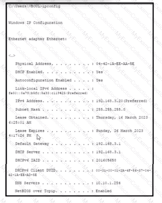
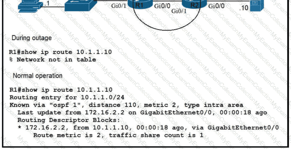
Refer to the exhibit. The user has connectivity to devices on network 192.168.3 0/24 but cannot reach users on the network 10.10.1.0724.
What is the first step to verify connectivity?
Question # 90
What are two characteristics of the distribution layer in a three-tier network architecture? (Choose two.)
Question # 91
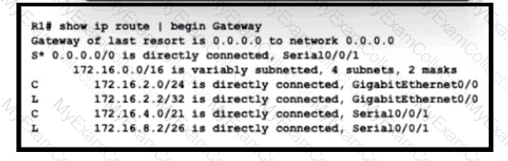
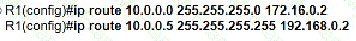
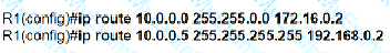
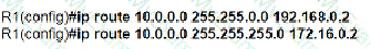
Refer to the exhibit. A packet sourced from 172.16.32.254 is destined for 172.16.32.8. What is the subnet mask of the preferred destination route?
Question # 92
In which two ways does a password manager reduce the chance of a hacker stealing a users password? (Choose two.)
Question # 94
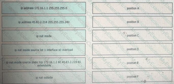
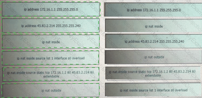
Refer to the exhibit.
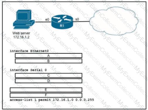
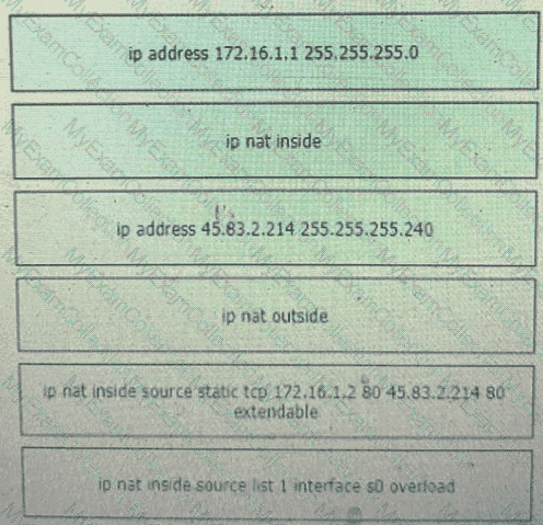
An engineer is configuring the router to provide static NAT for the webserver Drag and drop the configuration commands from the left onto the letters that correspond to its position in the configuration on the right.
Question # 95
An engineer is asked to protect unused ports that are configured in the default VLAN on a switch.
Which two steps will fulfill the request? (Choose two)
Question # 96
Which two capacities of Cisco DNA Center make it more extensible as compared to traditional campus device management? (Choose two)
Question # 98
Which API is used in controller-based architectures to interact with edge devices?
Question # 99
Refer to the exhibit.
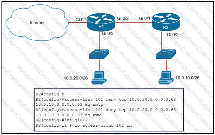
An extended ACL has been configured and applied to router R2 The configuration failed to work as intended Which two
changes stop outbound traffic on TCP ports 25 and 80 to 10.0.20 0 26 from the 10.0.10 0/26 subnet while still allowing all other traffic? (Choose
two )
Question # 100
What does a router do when configured with the default DNS lookup settings, and a URL is entered on the CLI?
Question # 101
Which command entered on a switch configured with Rapid PVST+ listens and learns for a specific time period?
Question # 102
Which command prevents passwords from being stored in the configuration as plain text on a router or switch?
Question # 104
Which command is used to specify the delay time in seconds for LLDP to initialize on any interface?
Question # 105
What facilitates a Telnet connection between devices by entering the device name?
Question # 106
An organization has decided to start using cloud-provided services. Which cloud service allows the organization to install its own operating system on a virtual machine?
Question # 107
How do TCP and UDP differ in the way they provide reliability for delivery of packets?
Question # 108
In which way does a spine-and-leaf architecture allow for scalability in a network when additional access ports are required?
Question # 110
When using Rapid PVST+, which command guarantees the switch is always the root bridge for VLAN 200?
Question # 111
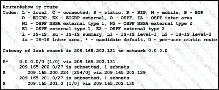
Refer to the exhibit.
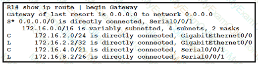
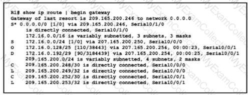
which path is used by the router for internet traffic ?
Question # 112
Refer to the exhibit.
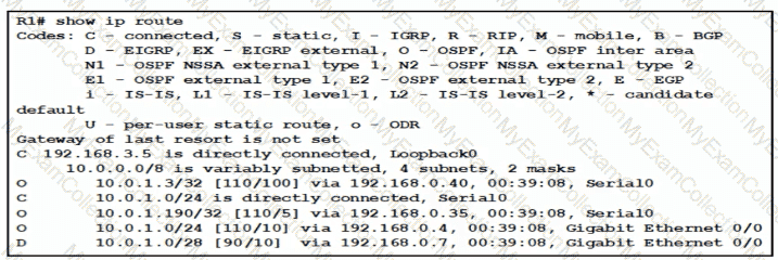
What is the next hop address for traffic that is destined to host 10.0.1.5?
Question # 113
Refer to the exhibit.
The network administrator wants VLAN 67 traffic to be untagged between Switch 1 and Switch 2 while all other VLANs are to remain tagged.
Which command accomplishes this task?
Question # 116
Which configuration ensures that the switch is always the root for VLAN 750?
Question # 117
Which network allows devices to communicate without the need to access the Internet?
Question # 123
Which two events occur automatically when a device is added to Cisco DNA Center? (Choose two. )
Question # 124
A router running EIGRP has learned the same route from two different paths. Which parameter does the router use to select the best path?
Question # 125
How does a Cisco Unified Wireless network respond to Wi-Fi channel overlap?
Question # 127
Drag and drop the TCP/IP protocols from the left onto the transmission protocols on the right

Question # 130
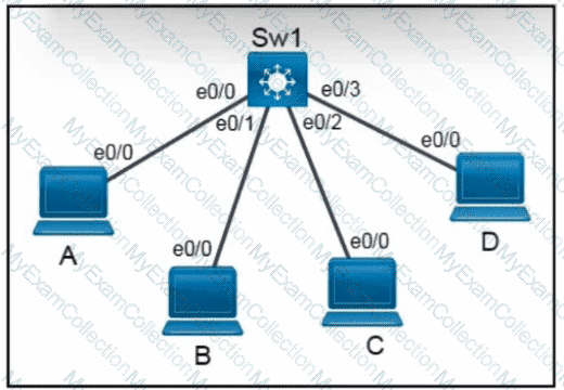
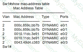
Refer to the exhibit.
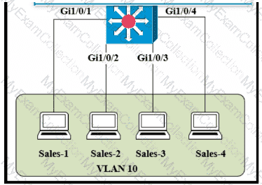
The entire contents of the MAC address table are shown. Sales-4 sends a data frame to Sales-1.
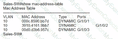
What does the switch do as it receives the frame from Sales-4?
Question # 131
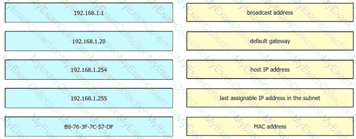
Refer to the exhibit.
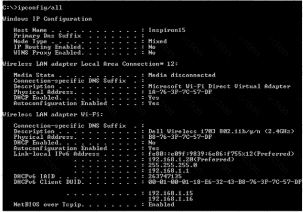
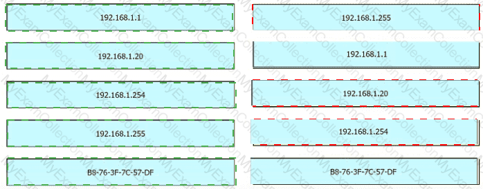
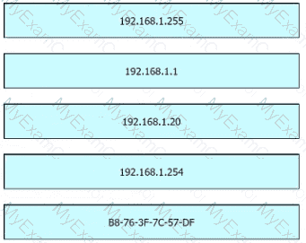
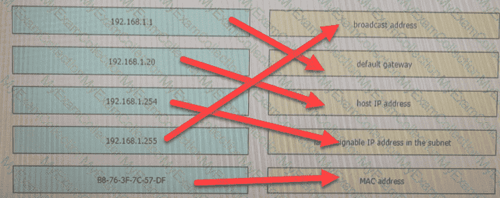
An engineer is tasked with verifying network configuration parameters on a client workstation to report back to the team lead. Drag and drop the node identifiers from the left onto the network parameters on the right.
Question # 132
Refer to the exhibit.
Router R1 Fa0/0 is unable ping router R3 Fa0/1.
Which action must be taken in router R1 to help resolve the configuration issue?
Question # 133
Which port type supports the spanning-tree portfast command without additional configuration?
Question # 135
What is the difference in data transmission delivery and reliability between TCP and UDP?
Question # 136
Which 802.11 frame type is indicated by a probe response after a client sends a probe request?
Question # 137
Refer to the exhibit.

Which route type does the routing protocol Code D represent in the output?
Question # 138
Refer to the exhibit.
Which prefix does Router 1 use for traffic to Host A?
Question # 139
A corporate office uses four floors in a building
• Floor 1 has 24 users
• Floor 2 has 29 users
• Floor 3 has 28 users
•Floor 4 has 22 users
Which subnet summarizes and gives the most efficient distribution of IP addresses for the router configuration?
Question # 140
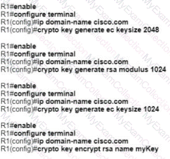
A network administrator must to configure SSH for remote access to router R1 The requirement is to use a public and private key pair to encrypt management traffic to and from the connecting client.
Which configuration, when applied, meets the requirements?
Question # 141
What makes Cisco DNA Center different from traditional network management applications and their management of networks?
Question # 142
With REST API, which standard HTTP header tells a server which media type is expected by the client?
Question # 144
Refer to the exhibit.
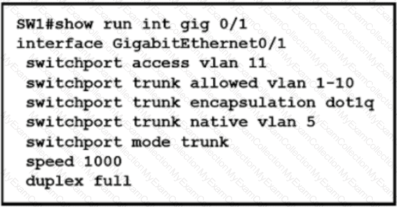
Which action is expected from SW1 when the untagged frame is received on the GigabitEthernet0/1 interface?
Question # 146
Refer to the exhibit.
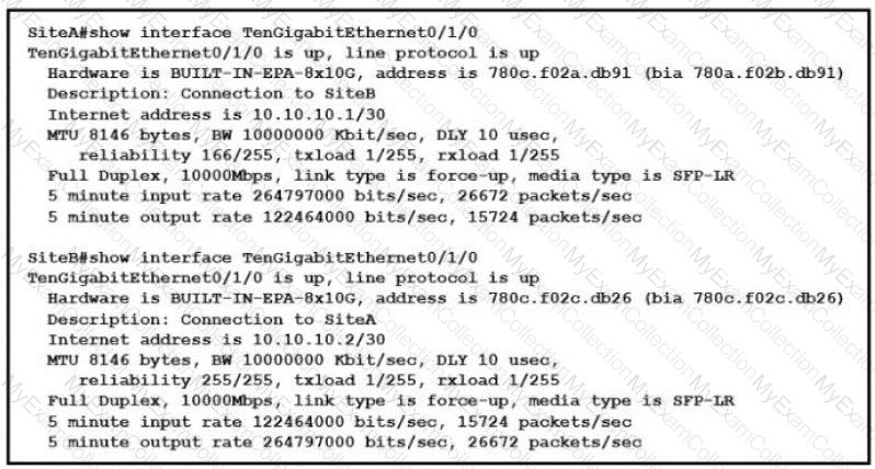
Shortly after SiteA was connected to SiteB over a new single-mode fiber path users at SiteA report intermittent connectivity issues with applications hosted at SiteB What is the cause of the intermittent connectivity issue?
Question # 147
A user configured OSPF in a single area between two routers A serial interface connecting R1 and R2 is running encapsulation PPP By default which OSPF network type is seen on this interface when the user types show ip ospf interface on R1 or R2?
Question # 148
An engineer configured an OSPF neighbor as a designated router. Which state verifies the designated router is in the proper mode?
Question # 151
An engineer must configure a WLAN using the strongest encryption type for WPA2- PSK. Which cipher fulfills the configuration requirement?
Question # 152
What are two recommendations for protecting network ports from being exploited when located in an office space outside of an IT closer? (Choose two.)
Question # 158
When a WLAN with WPA2 PSK is configured in the Wireless LAN Controller GUI which format is supported?
Question # 159
Refer to the exhibit.
What is the metric of the route to the 192.168.10.33/28 subnet?
Question # 160
What does an SDN controller use as a communication protocol to relay forwarding changes to a southbound API?
Question # 161
Refer to the exhibit.
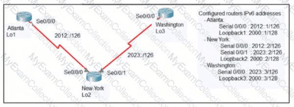
An engineer configured the New York router with static routes that point to the Atlanta and Washington sites. When command must be configured on the Atlanta and Washington routers so that both sites are able to reach the loopback2 interface on the New York router?
Question # 163
Which mode must be set for APs to communicate to a Wireless LAN Controller using the Control and Provisioning of Wireless Access Points (CAPWAP) protocol?
Question # 164
Which two tasks must be performed to configure NTP to a trusted server in client mode on a single network device? (Choose two)
Question # 165
Refer to the exhibit.
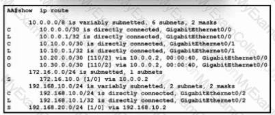
With which metric was the route to host 172.16.0.202 learned?
Question # 166
Refer to the exhibit.
An engineer deploys a topology in which R1 obtains its IP configuration from DHCP. If
the switch and DHCP server configurations are complete and correct. Which two sets of commands must be configured on R1 and R2 to complete the task? (Choose two)
Question # 169
A network analyst is tasked with configure the date and time on a router using EXEC mode. The date must be set to 12:00am. Which command should be used?
Question # 170
Refer to the exhibit.
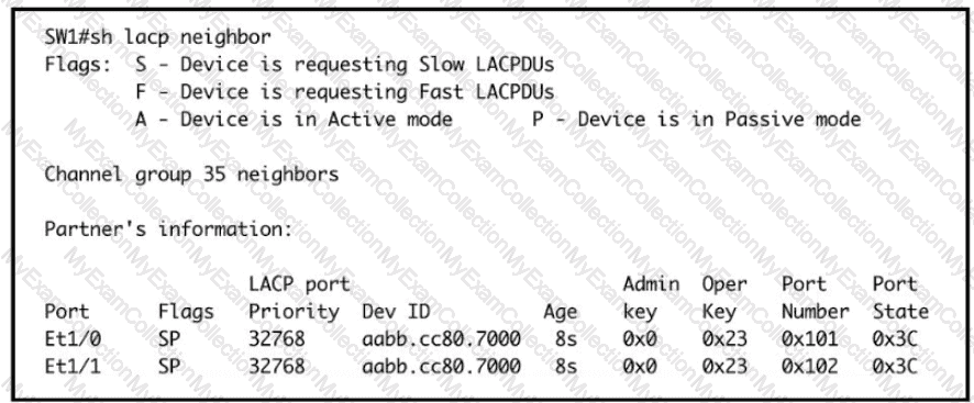
Based on the LACP neighbor status, in which mode is the SW1 port channel configured?
Question # 171
How does CAPWAP communicate between an access point in local mode and a WLC?
Question # 172
After installing a new Cisco ISE server, which task must the engineer perform on the Cisco WLC to connect wireless clients on a specific VLAN based on their credentials?
Question # 173
If a switch port receives a new frame while it is actively transmitting a previous frame, how does it process the frames?
Question # 174
The service password-encryption command is entered on a router. What is the effect of this configuration?
Question # 175
What is the same for both copper and fiber interfaces when using SFP modules?
Question # 176
What is the primary different between AAA authentication and authorization?
Question # 177
Refer to the exhibit.
Which command configures a floating static route to provide a backup to the primary link?
Question # 178
When a switch receives a frame for a known destination MAC address, how is the frame handed?
Question # 179
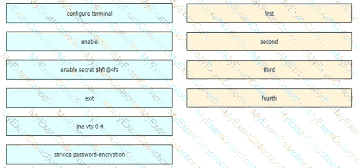
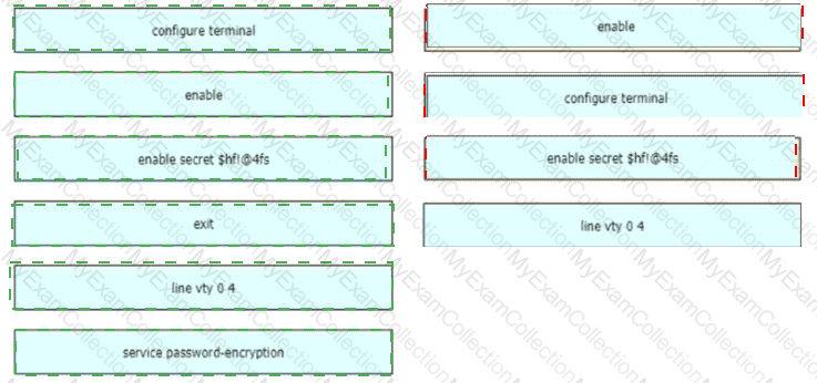
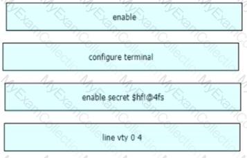
An engineer is configuring an encrypted password for the enable command on a router where the local user database has already been configured Drag and drop the configuration commands from the left into the correct sequence on the right Not all commands are used
Question # 180
How do traditional campus device management and Cisco DNA Center device management differ in regards to deployment?
Question # 181
Refer to the exhibit.
If configuring a static default route on the router with the ip route 0.0.0.0 0.0.0.0 10.13.0.1 120 command how does the router respond?
Question # 182
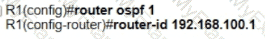
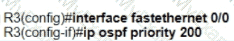
Refer to the exhibit.
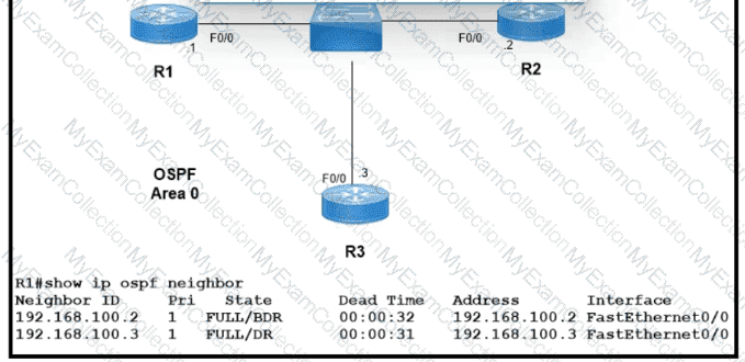
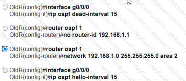
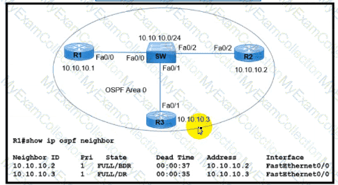
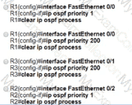
Which two configurations must the engineer apply on this network so that R1 becomes the DR? (Choose two.)
A)
B)

C)

D)

E)
Question # 183
Which command must be entered when a device is configured as an NTP server?
Question # 185
Refer to the exhibit.
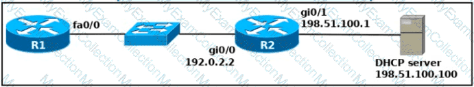
An engineer is configuring a new router on the network and applied this configuration. Which additional configuration allows the PC to obtain its IP address from a DHCP server?

Question # 187
Refer to the exhibit.
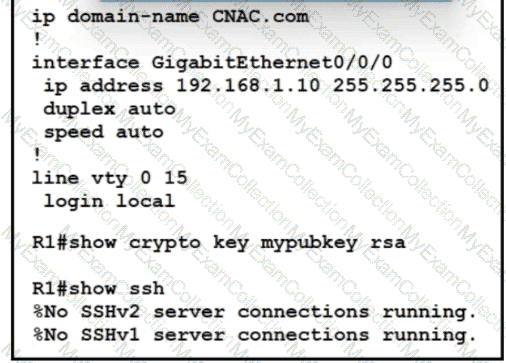
Which two commands must be added to update the configuration of router R1 so that it accepts only encrypted connections? (Choose two )
Question # 188
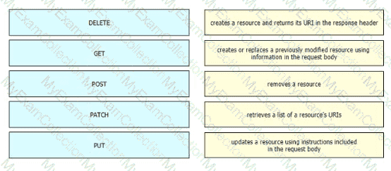
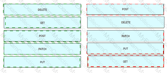
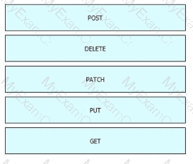
Drag and drop the HTTP methods used with REST-Based APIs from the left onto the descriptions on the right.
Question # 189
Refer to the exhibit.
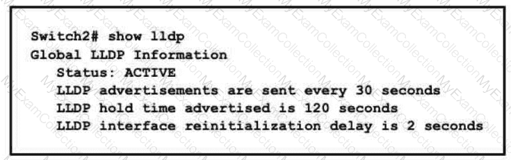
A network engineer must update the configuration on Switch2 so that it sends LLDP packets every minute and the information sent via LLDP is refreshed every 3 minutes Which configuration must the engineer apply?
A)

B)

C)

D)

Question # 190
Refer to the exhibit.
All VLANs are present in the VLAN database. Which command sequence must be applied to complete the configuration?
Question # 191
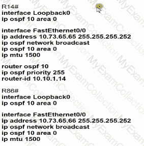
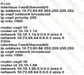
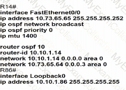
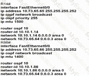
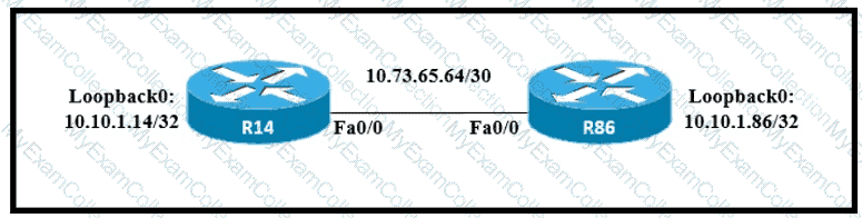
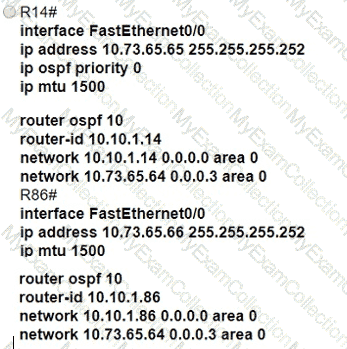
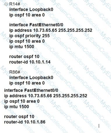
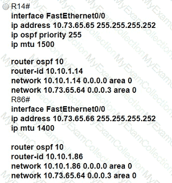
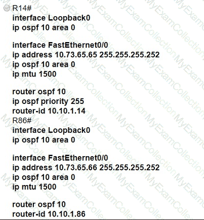
Refer to the exhibit.

Which configuration allows routers R14 and R86 to form an OSPFv2 adjacency while acting as a central point for exchanging OSPF information between routers?
A)
B)
C)
D)
Question # 192
Refer to the exhibit.
Which command configures OSPF on the point-to-point link between routers R1 and R2?
Question # 193
Which WLC management connection type is vulnerable to man-in-the-middle attacks?
Question # 195
Refer to the exhibit.
Which route must be configured on R1 so that OSPF routing is used when OSPF is up. but the server is still reachable when OSPF goes down?
Question # 196
An engineer must configure neighbor discovery between the company router and an ISP

What is the next step to complete the configuration if the ISP uses a third-party router?
Question # 197
Which two wireless security standards use Counter Mode with Cipher Block Chaining Message Authentication Code Protocol for encryption and data integrity ' ? (Choose two.)
Question # 198
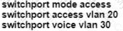
A Cisco engineer must configure a single switch interface to meet these requirements
• accept untagged frames and place them in VLAN 20
• accept tagged frames in VLAN 30 when CDP detects a Cisco IP phone
Which command set must the engineer apply?
A)

B)

C)
D)

Question # 201
A network engineer is configuring a switch so that it is remotely reachable via SSH. The engineer has already configured the host name on the router. Which additional command must the engineer configure before entering the command to generate the RSA key?
Question # 202
Refer to the exhibit.
All interfaces are configured with duplex auto and ip ospf network broadcast. Which configuration allows routers R14 and R86 to form an OSPFv2 adjacency and act as a central point for exchanging OSPF information between routers?
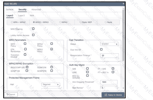
Question # 203
Refer to the exhibit.
Users need to connect to the wireless network with IEEE 802.11r-compatible devices. The connection must be maintained as users travel between floors or to other areas in the building What must be the configuration of the connection?
Question # 204
An engineer must configure R1 for a new user account. The account must meet these requirements:
* It must be configured in the local database.
* The username is engineer.
* It must use the strongest password configurable. Which command must the engineer configure on the router?
Question # 206
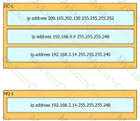
Refer to Exhibit.
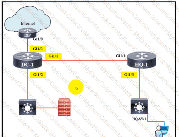
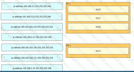
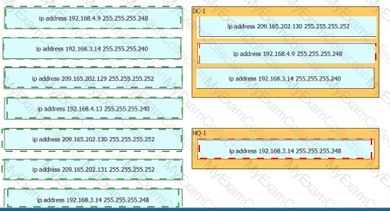
Rotor to the exhibit. The IP address configurations must be completed on the DC-1 and HQ-1 routers based on these requirements:
DC-1 Gi1/0 must be the last usable address on a /30
DC-1 Gi1/1 must be the first usable address on a /29
DC-1 Gi1/2 must be the last usable address on a /28
HQ-1 Gil/3 must be the last usable address on a /29
Drag and drop the commands from the left onto the destination interfaces on the right. Not all commands are used
Question # 207
Which type of IPv6 address is similar to a unicast address but is assigned to multiple devices on the same network at the same time?
Question # 208
Refer to the exhibit.
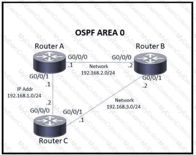
Which action must be taken to ensure that router A is elected as the DR for OSPF area 0?
Question # 209
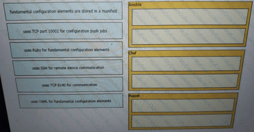
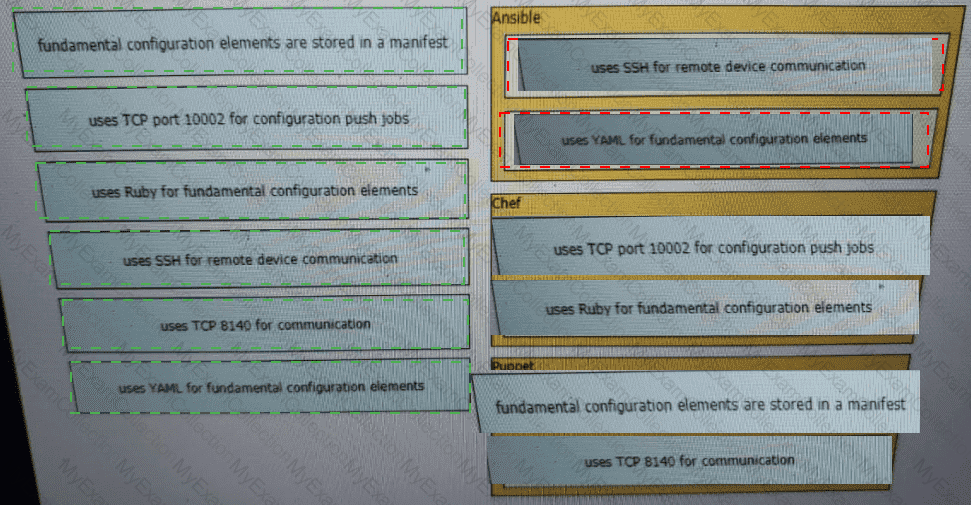
Drag and drop the descriptions from the left onto the configuration-management technologies on the right.
Question # 213
Which characteristic differentiates the concept of authentication from authorization and accounting?
Question # 214
Refer to the exhibit.

R1 learns all routes via OSPF Which command configures a backup static route on R1 to reach the 192 168.20.0/24 network via R3?
Question # 216
What is an expected outcome when network management automation is deployed?
Question # 217
A network engineer is installing an IPv6-only capable device. The client has requested that the device IP address be reachable only from the internal network. Which type of IPv6 address must the engineer assign?
Question # 218
Which two spanning-tree states are bypassed on an interface running PortFast? (Choose two.)
Question # 219
Refer to the exhibit.
R1 has taken the DROTHER role in the OSPF DR/BDR election process. Which configuration must an engineer implement so that R1 is elected as the DR?
Question # 220
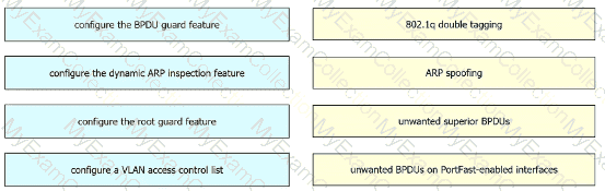
Drag and drop the threat-mitigation techniques from the left onto the types of threat or attack they mitigate on the right.
Question # 221
Drag and drop the TCP or UDP details from the left onto their corresponding protocols on the right.
Question # 222
Refer to the exhibit.
Traffic sourced from the loopback0 Interface is trying to connect via ssh to the host at 10.0.1.15. What Is the next hop to the destination address?
Question # 223
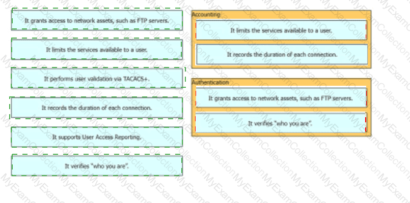
Drag and drop the AAA terms from the left onto the description on the right.


Question # 225
An organization secures its network with multi-factor authentication using an authenticator app on employee smartphone. How is the application secured in the case of a user’s smartphone being lost or stolen?
Question # 226
Refer to the exhibit.
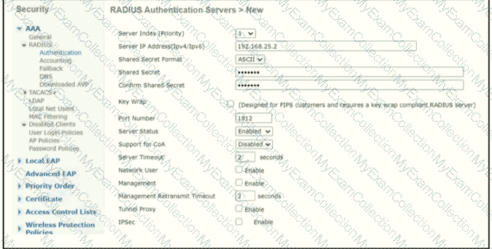
A network engineer configures the Cisco WLC to authenticate local wireless clients against a RADIUS server Which task must be performed to complete the process?
Question # 227
Refer to the exhibit.
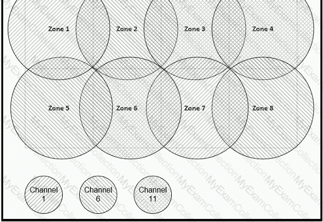
Between which zones do wireless users expect to experience intermittent connectivity?
Question # 228
Refer to the exhibit. An engineer is asked to configure router R1 so that it forms an OSPF single-area neighbor relationship with R2. Which command sequence must be implemented to configure the router?
Question # 229
Refer to the exhibit.
The administrator must configure a floating static default route that points to 2001:db8:1234:2::1 and replaces the current default route only if it fails. Which command must the engineer configure on the CPE?
Question # 230
Refer to the exhibit.

Which two commands when used together create port channel 10? (Choose two.)
Question # 231
Which protocol requires authentication to transfer a backup configuration file from a router to a remote server?
Question # 232
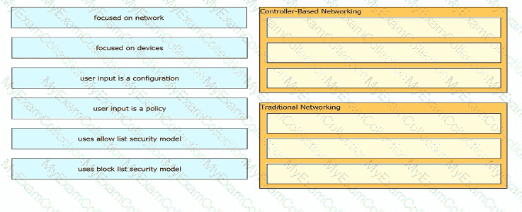
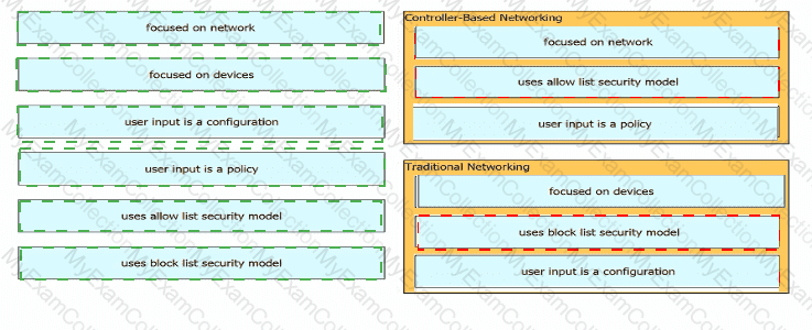
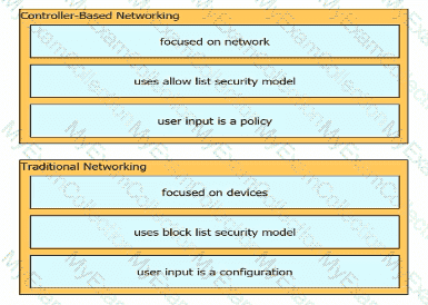
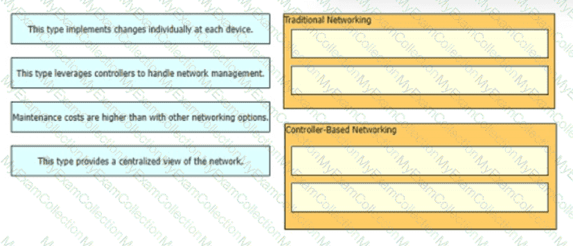
Drag and drop the characteristics of networking from the left onto the networking types on the right.
Question # 233
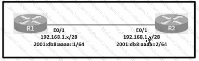
Configure IPv4 and IPv6 connectivity between two routers. For IPv4, use a /28 network from the 192.168.1.0/24 private range. For IPv6, use the first /64 subnet from the 2001:0db8:aaaa::/48 subnet.
1. Using Ethernet0/1 on routers R1 and R2, configure the next usable/28 from the 192.168.1.0/24 range. The network 192.168.1.0/28 is unavailable.
2. For the IPv4 /28 subnet, router R1 must be configured with the first usable host address.
3. For the IPv4 /28 subnet, router R2 must be configured with the last usable host address.
4. For the IPv6 /64 subnet, configure the routers with the IP addressing provided from the topology.
5. A ping must work between the routers on the IPv4 and IPv6 address ranges.
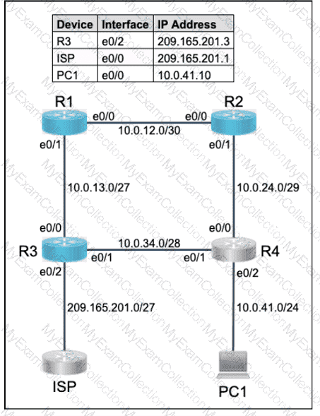
Question # 234
All physical cabling is in place. Router R4 and PCI are fully configured and
inaccessible. R4 ' s WAN interfaces use .4 in the last octet for each subnet.
Configurations should ensure that connectivity is established end-to-end.
1 . Configure static routing to ensure RI prefers the path through R2 to
reach only PCI on R4 ' s LAN
2. Configure static routing that ensures traffic sourced from RI will take
an alternate path through R3 to PCI in the event of an outage along
the primary path
3. Configure default routes on RI and R3 to the Internet using the least number of hops
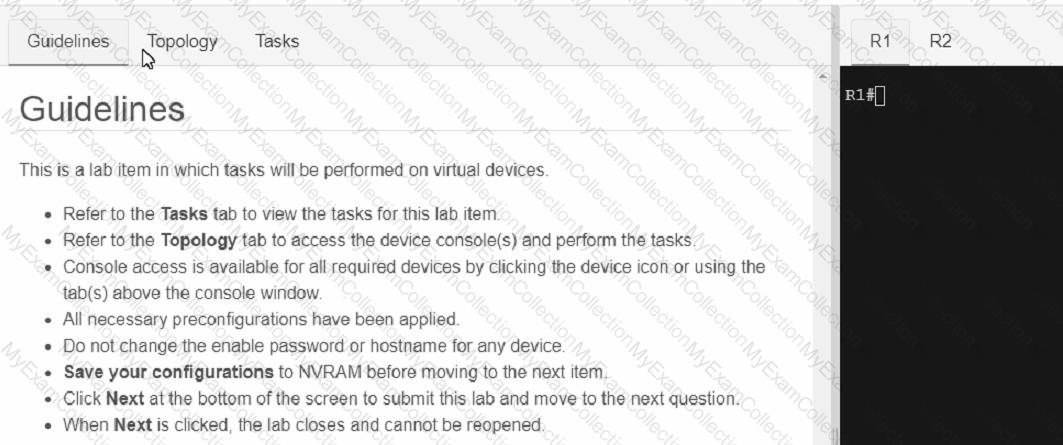
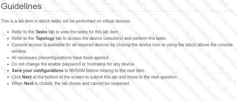
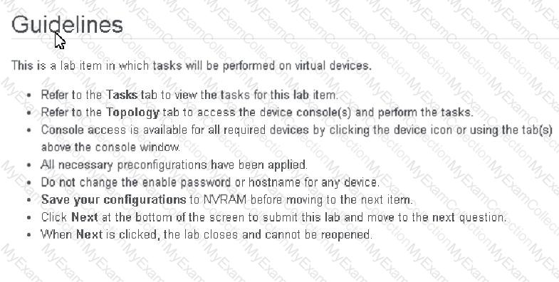
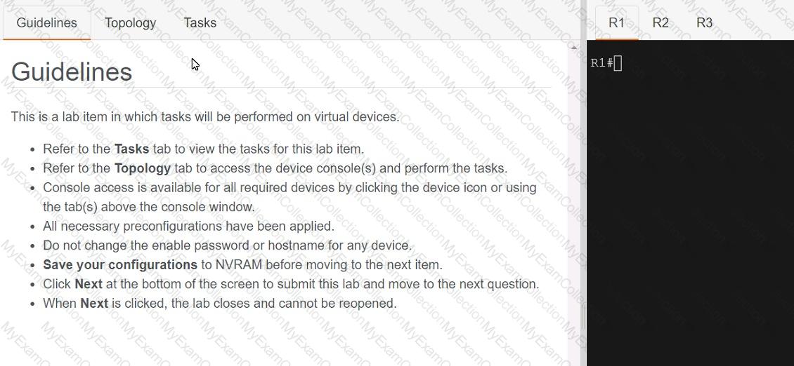
Guidelines
This is a lab item in which tasks will be performed on virtual devices.
• Refer to the Tasks tab to view the tasks for this lab item.
• Refer to the Topology tab to access the device console(s) and perform the tasks.
• Console access is available for all required devices by clicking the device icon or using
the tab(s) above the console window.
• All necessary preconfigurations have been applied.
• Do not change the enable password or hostname for any device.
• Save your configurations to NVRAM before moving to the next item.
• Click Next at the bottom of the screen to submit this lab and move to the next question.
• When Next is clicked, the lab closes and cannot be reopened.
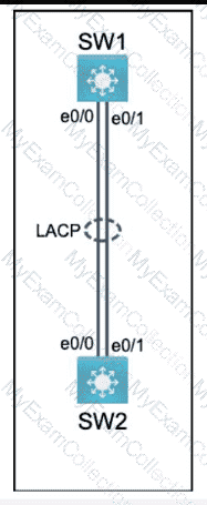
Question # 235
Physical connectivity is implemented between the two Layer 2 switches,
and the network connectivity between them must be configured.
I . Configure an LACP EtherChanneI and number it as 44; configure it
between switches SWI and SW2 using interfaces EthernetO/O and
Ethernet0/1 on both sides. The LACP mode must match on both ends.
2. Configure the EtherChanneI as a trunk link.
3. Configure the trunk link with 802. Iq tags.
4. Configure VLAN ' MONITORING ' as the untagged VLAN of the
EtherChannel.
==================
Guidelines
This is a lab item in which tasks will be performed on virtual devices.
• Refer to the Tasks tab to view the tasks for this lab item.
• Refer to the Topology tab to access the device console(s) and perform the tasks.
• Console access is available for all required devices by clicking the device icon or using
the tab(s) above the console window.
• All necessary preconfigurations have been applied.
• Do not change the enable password or hostname for any device.
• Save your configurations to NVRAM before moving to the next item.
• Click Next at the bottom of the screen to submit this lab and move to the next question.
• When Next is clicked, the lab closes and cannot be reopened.
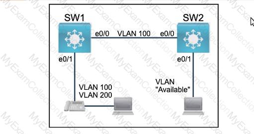
Question # 236
All physical cabling between the two switches is installed. Configure the network connectivity between the switches using the designated VLANs and interfaces.
1. Configure VLAN 100 named Compute and VLAN 200 named Telephony where required for each task.
2. Configure Ethernet0/1 on SW2 to use the existing VLAN named Available.
3. Configure the connection between the switches using access ports.
4. Configure Ethernet0/1 on SW1 using data and voice VLANs.
5. Configure Ethemet0/1 on SW2 so that the Cisco proprietary neighbor discovery protocol is turned off for the designated interface only.
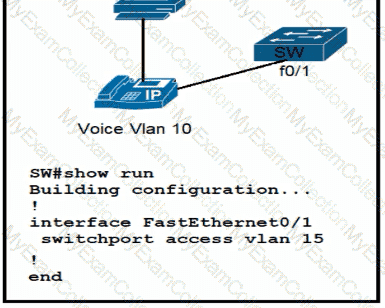
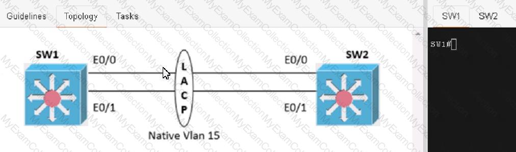
Question # 237
Physical connectivity is implemented between the two Layer 2 switches, and the network connectivity between them must be configured
1. Configure an LACP EtherChannel and number it as 1; configure it between switches SW1 and SVV2 using interfaces Ethernet0/0 and Ethernet0/1 on both sides. The LACP mode must match on both ends
2 Configure the EtherChannel as a trunk link.
3. Configure the trunk link with 802.1 q tags.
4. Configure the native VLAN of the EtherChannel as VLAN 15.
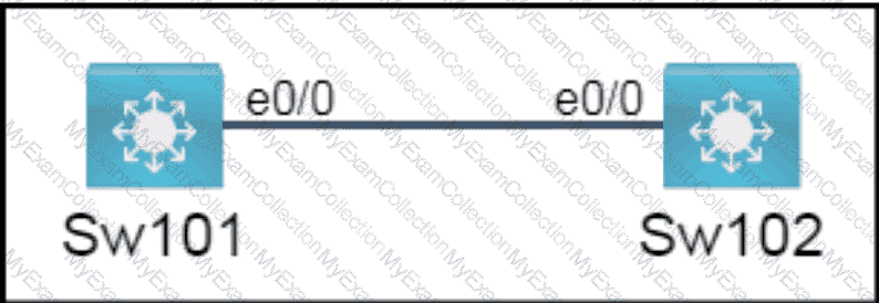
Question # 238
All physical cabling is in place. A company plans to deploy 32 new sites.
The sites will utilize both IPv4 and IPv6 networks.
1 . Subnet 172.25.0.0/16 to meet the subnet requirements and maximize
the number of hosts
Using the second subnet
• Assign the first usable IP address to e0/0 on Sw1O1
• Assign the last usable IP address to e0/0 on Sw102
2. Subnet to meet the subnet requirements and maximize
the number of hosts
c Using the second subnet
• Assign an IPv6 GUA using a unique 64-Bit interface identifier
on e0/0 on Sw101
• Assign an IPv6 GUA using a unique 64-Bit interface identifier
on eO/O on swi02
Guidelines
This is a lab item in which tasks will be performed on virtual devices.
• Refer to the Tasks tab to view the tasks for this lab item.
• Refer to the Topology tab to access the device console(s) and perform the tasks.
• Console access is available for all required devices by clicking the device icon or using
the tab(s) above the console window.
• All necessary preconfigurations have been applied.
• Do not change the enable password or hostname for any device.
• Save your configurations to NVRAM before moving to the next item.
• Click Next at the bottom of the screen to submit this lab and move to the next question.
• When Next is clicked, the lab closes and cannot be reopened.
Question # 239
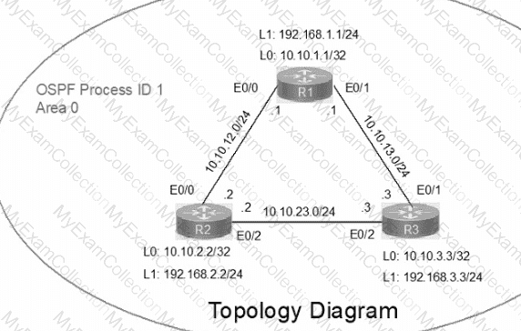
IP connectivity between the three routers is configured. OSPF adjacencies must be established.
1. Configure R1 and R2 Router IDs using the interface IP addresses from the link that is shared between them.
2. Configure the R2 links with a max value facing R1 and R3. R2 must become the DR. R1 and R3 links facing R2 must remain with the default OSPF configuration for DR election. Verify the configuration after clearing the OSPF process.
3. Using a host wildcard mask, configure all three routers to advertise their respective Loopback1 networks.
4. Configure the link between R1 and R3 to disable their ability to add other OSPF routers.
Question # 240
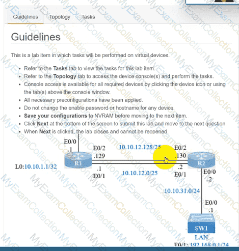
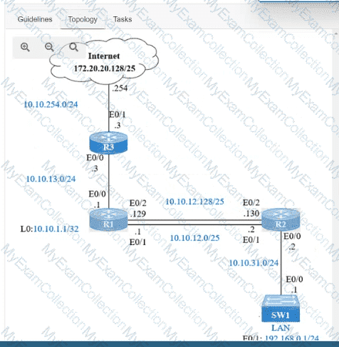
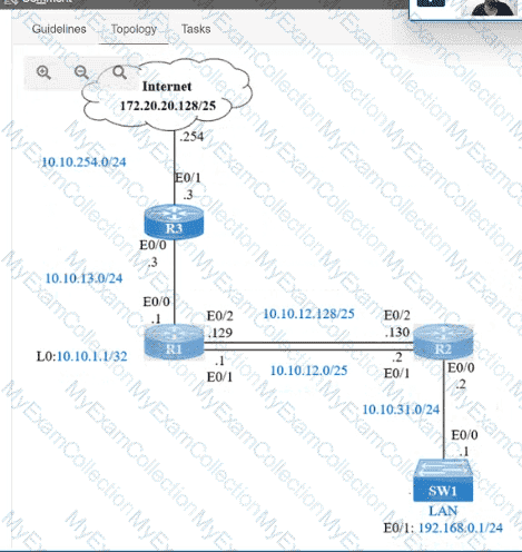
IP connectivity and OSPF are preconfigured on all devices where necessary. Do not make any changes to the IP addressing or OSPF. The company policy uses connected interfaces and next hops when configuring static routes except for load balancing or redundancy without floating static. Connectivity must be established between subnet 172.20.20.128/25 on the Internet and the LAN at 192.168.0.0/24 connected to SW1:
1. Configure reachability to the switch SW1 LAN subnet in router R2.
2. Configure default reachability to the Internet subnet in router R1.
3. Configure a single static route in router R2 to reach to the Internet subnet considering both redundant links between routers R1 and R2. A default route is NOT allowed in router R2.
4. Configure a static route in router R1 toward the switch SW1 LAN subnet where the primary link must be through Ethernet0/1. and the backup link must be through Ethernet0/2 using a floating route. Use the minimal administrative distance value when required.
Question # 241
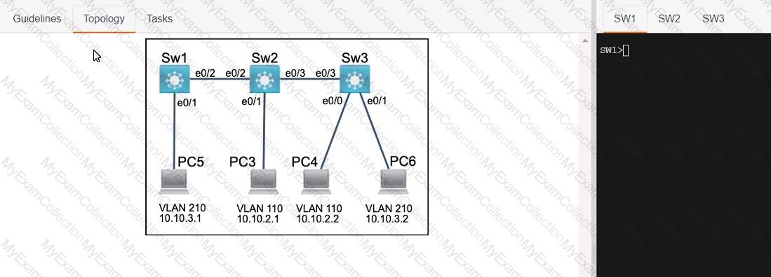
Three switches must be configured for Layer 2 connectivity. The company requires only the designated VLANs to be configured on their respective switches and permitted accross any links between switches for security purposes. Do not modify or delete VTP configurations.
The network needs two user-defined VLANs configured:
VLAN 110: MARKETING
VLAN 210: FINANCE
1. Configure the VLANs on the designated switches and assign them as access ports to the interfaces connected to the PCs.
2. Configure the e0/2 interfaces on Sw1 and Sw2 as 802.1q trunks with only the required VLANs permitted.
3. Configure the e0/3 interfaces on Sw2 and Sw3 as 802.1q trunks with only the required VLANs permitted.
Question # 242
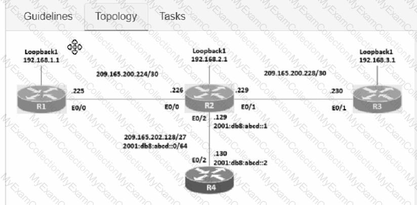
Connectivity between four routers has been established. IP connectivity must be configured in the order presented to complete the implementation. No dynamic routing protocols are included.
1. Configure static routing using host routes to establish connectivity from router R3 to the router R1 Loopback address using the source IP of 209.165.200.230.
2. Configure an IPv4 default route on router R2 destined for router R4.
3. Configure an IPv6 default router on router R2 destined for router R4.
Question # 243
Topology:
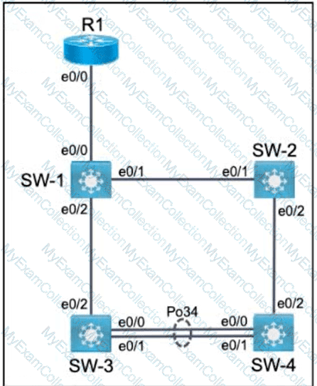
All relevant ports are preconfigured as IEEE 802.1Q trunks.
Task 1
Configure SW-1 port Ethernet0/0 to permit only VLANs 5 and 6.
Task 2
Configure ports Ethernet0/1 on SW-1 and SW-2 to use VLAN 77 as the native VLAN.
Task 3
Configure SW-2 port Ethernet0/2 to permit only VLAN 6.
Task 4
Using LACP, create a Port-Channel between SW-3 and SW-4.
Combine Ethernet0/0 and Ethernet0/1 into a Port-Channel while leaving the existing trunk configurations intact.
Assign Port-Channel number 34.
Only SW-3 must initiate LACP negotiations.
Question # 244
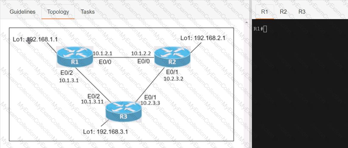
Connectivity between three routers has been established, and IP services must be configured jn the order presented to complete the implementation Tasks assigned include configuration of NAT, NTP, DHCP, and SSH services.
1. All traffic sent from R3 to the R1 Loopback address must be configured for NAT on R2. All source addresses must be translated from R3 to the IP address of Ethernet0/0 on R2, while using only a standard access list named NAT To verify, a ping must be successful to the R1 Loopback address sourced from R3. Do not use NVI NAT configuration.
2. Configure R1 as an NTP server and R2 as a client, not as a peer, using the IP address of the R1 Ethernet0/2 interface. Set the clock on the NTP server for midnight on January 1, 2019.
3. Configure R1 as a DHCP server for the network 10.1.3.0/24 in a pool named TEST. Using a single command, exclude addresses 1-10 from the range. Interface Ethernet0/2 on R3 must be issued the IP address of 10.1.3.11 via DHCP.
4. Configure SSH connectivity from R1 to R3, while excluding access via other remote connection protocols. Access for user root and password Cisco must be set on router R3 using RSA and 1024 bits. Verify connectivity using an SSH session from router R1 using a destination address of 10.1.3.11. Do NOT modify console access or line numbers to accomplish this task.
Question # 245
Topology:
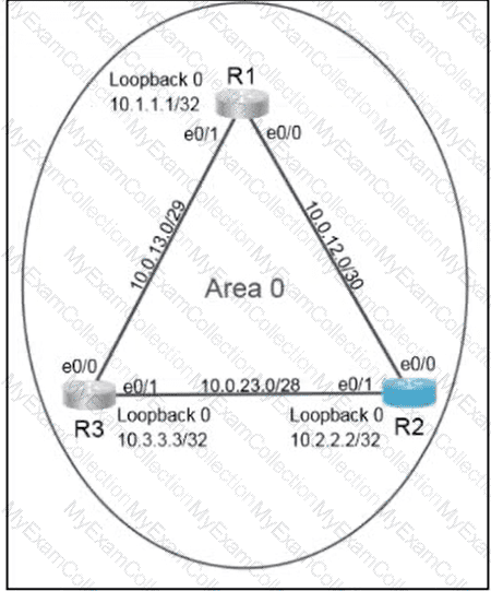
Configure OSPF routing for the network by completing the following tasks:
Task 1
Configure OSPF on R2. Ensure that R1 and R3 become neighbors.
Use process ID 30.
Use 10.22.22.22 as the router ID.
Under the OSPF process, advertise the following specific prefixes:
10.0.23.0/28
10.0.12.0/30
Task 2
Ensure that R2 always becomes the designated router (DR).
Question # 246
Refer to the exhibit.
The EtherChannel is configured with a speed of 1000 and duplex as full on both ends of channel group 1. What is the next step to configure the channel on switch A to respond to but not initiate LACP communication?
Question # 248
A WLC sends alarms about a rogue AP, and the network administrator verifies that the alarms are caused by a legitimate autonomous AP.
Question # 249
When a WPA2-PSK WLAN is configured in the Wireless LAN Controller, what is the minimum number of characters that is required in ASCII format?
Question # 250
Which command configures the Cisco WLC to prevent a serial session with the WLC CLI from being automatical togged out?
Question # 251
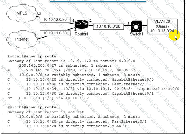
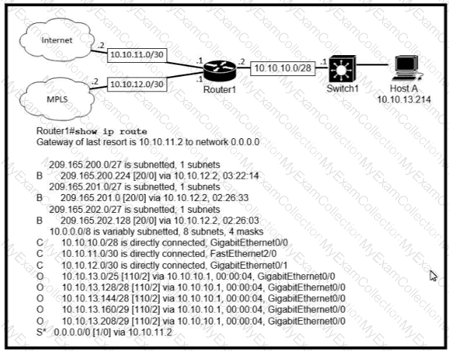
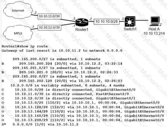
Refer to the exhibit.
An administrator received a call from a branch office regarding poor application performance hosted at the headquarters. Ethernet 1 is connected between Router1 and the LAN switch. What identifies the issue?
Question # 252
Which two IPv6 addresses are used to provide connectivity between two routers on a shared link? (Choose two)
Question # 255
A network engineer is upgrading a small data center to host several new applications, including server backups that are expected to account for up to 90% of the bandwidth during peak times. The data center connects to the MPLS network provider via a primary circuit and a secondary circuit. How does the engineer inexpensively update the data center to avoid saturation of the primary circuit by traffic associated with the backups?
Question # 256
Which action implements physical access control as part of the security program of an organization??
Question # 257
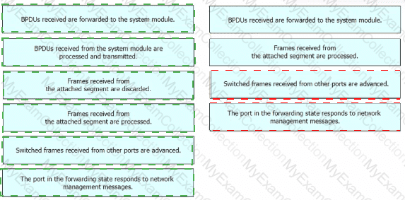
Drag and drop the Rapid PVST+ forwarding state actions from the left to the right. Not all actions are used.

Question # 258
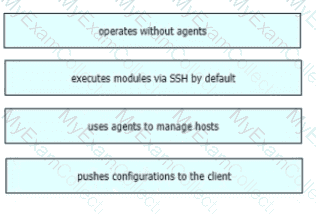
Drag and drop the Ansible features from the left to the right Not all features are used.
Question # 259
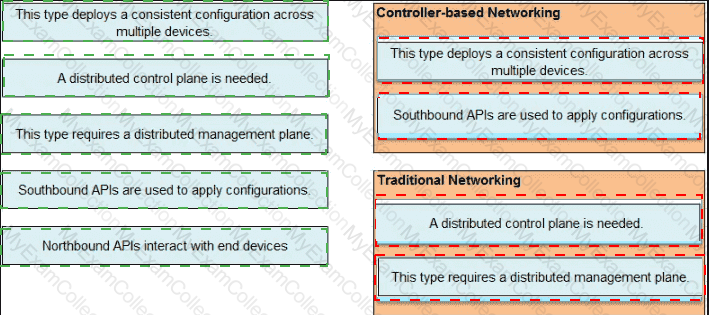
Drag and drop the statements about networking from the left onto the corresponding networking types on the right
Question # 261
Which type of IPv4 address type helps to conserve the globally unique address classes?
Question # 262
Refer to the exhibit.
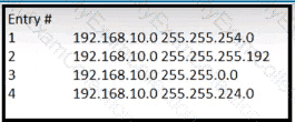
Which entry is the longest prefix match for host IP address 192.168.10.5?
Question # 263
hostname CPE
service password-encryption
ip domain name ccna.cisco.com
ip name-server 198.51.100.210
crypto key generate rsa modulus 1024
username admin privilege 15 secret s0m3s3cr3t
line vty 0 4
transport input ssh
login local
Refer to the exhibit. An engineer executed the script and added commands that were not necessary for SSH and now must remove the commands. Which two commands must be executed to correct the configuration? (Choose two.)
Question # 265
Refer to the exhibit.
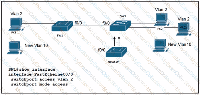
An engineer is configuring a new Cisco switch NewSW, to replace SW2 The details have been provided
• Switches SW1 and SW2 are third-party devices without support for trunk ports
• The existing connections must be maintained between PC1 PC2 and PC3
• Allow the switch to pass traffic from future VLAN 10. Which configuration must be applied?
A)

B)

C)

D)

Question # 266
Which IP header field is changed by a Cisco device when QoS marking is enabled?
Question # 267
What must be considered for a locally switched FlexConnect AP if the VLANs that are used by the AP and client access are different?
Question # 269
Refer to the exhibit.
What is the prefix length for the route that router1 will use to reach host A?
Question # 270
Refer to the exhibit.
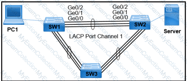
PC1 regularly sends 1800 Mbps of traffic to the server. A network engineer needs to configure the EtherChannel to disable Port Channel 1 between SW1 and SW2 when the Ge0/0 and Ge0/1 ports on SW2 go down. Which configuration must the engineer apply to the switch?
A)

B)

C)

D)

Question # 271
Which type of port is used to connect to the wired network when an autonomous AP maps two VLANs to its WLANs?
Question # 272
Which protocol is used in Software Defined Access (SDA) to provide a tunnel between two edge nodes in different fabrics?
Question # 274
What is the purpose of configuring different levels of syslog for different devices on the network?
Question # 275
Refer to the exhibit.
User traffic originating within site 0 is failing to reach an application hosted on IIP address 192.168.0.10. Which is located within site A What is determined by the routing table?
Question # 276
Which two features introduced in SNMPv2 provide the ability to retrieve large amounts of data in one request
Question # 278
Which protocol must be implemented to support separate authorization and authentication solutions for wireless APs?
Question # 279
Refer to the exhibit.
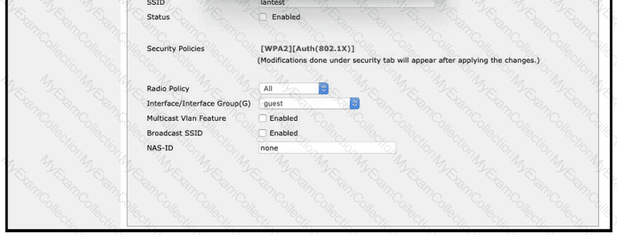
A Cisco engineer creates a new WLAN called lantest. Which two actions must be performed so that only high-speed 2.4-GHz clients connect? (Choose two.)
Question # 280
Drag and drop the characteristics of transport layer protocols from the left onto the corresponding protocols on the right.
Question # 282
Which cable type must be used to interconnect one switch using 1000 BASE-SX GBIC modules and another switch using 1000 BASE-SX SFP modules?


Question # 286
Refer to the exhibit.
Which configuration establishes a Layer 2 LACP EtherChannel when applied to both switches?
Question # 288
Drag and drop the WLAN components from the left onto the component details on the right.
Question # 289
By default, how long will the switch continue to know a workstation MAC address after the workstation stops sending traffic?
Question # 291
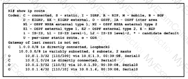
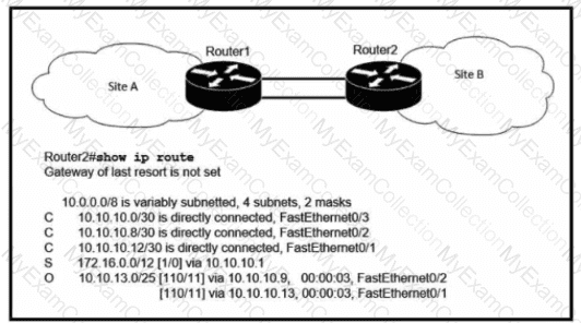
Refer to the exhibit.

A network engineer executes the show ip route command on router D. What is the next hop to network 192.168.1.0/24 and why?
Question # 293
What is a reason to configure a trunk port that connects to a WLC distribution port?
Question # 294
Which Cisco proprietary protocol ensures traffic recovers immediately, transparently, and automatically when edge devices or access circuits fail?
Question # 295
What is used as a solution for protecting an individual network endpoint from attack?
Question # 296
Refer to the exhibit.
Host A switch interface is configured in VLAN 2. Host D sends a unicast packet destined for the IP address of host A.
What does the switch do when it receives the frame from host D?
Question # 297
SIP-based Call Admission Control must be configuredd in the Cisco WLC GUI. SIP call-snooping ports are configured. Which two actions must be completed next? (Choose two.)
Question # 298
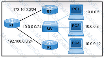
Refer to the exhibit.
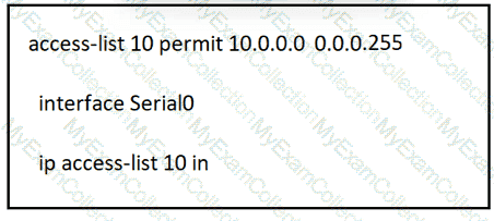
A network administrator must permit traffic from the 10.10.0.0/24 subnet to the WAN on interface Serial0. What is the effect of the configuration as the administrator applies the command?
Question # 299
Refer to the exhibit.
A network engineer must configure R1 so that it sends all packets destined to the 10.0.0.0/24 network to R3, and all packets destined to PCI to R2. Which configuration must the engineer implement?
A)
B)
C)

D)
Question # 300
Drag and drop the statements about networking from the left onto the corresponding networking types on the right. Not all statements are used.
Question # 301
Which interface enables communication between a program on the controller and a program on the networking devices?
Question # 302
PC1 tries to send traffic to newly installed PC2. The PC2 MAC address is not listed in the MAC address table of the switch, so the switch sends the packet to all ports in the same VLAN Which switching concept does this describe?
Question # 303
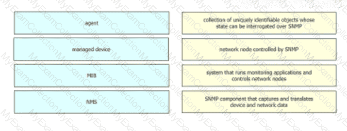
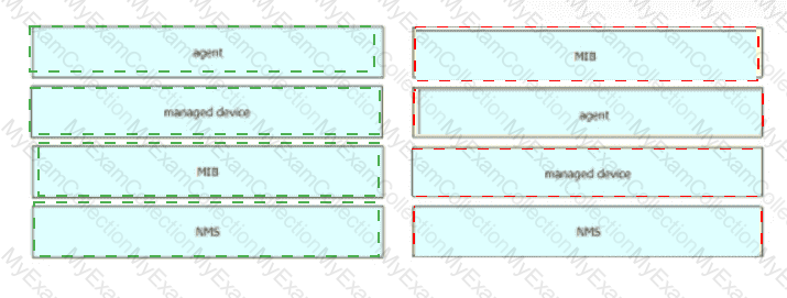
Drag and drop the SNMP components from the left onto the description on the right.
Question # 304
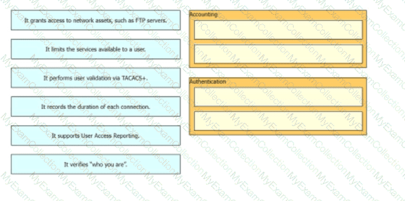
Drag and drop the statements about AAA services from the left onto the corresponding AAA services on the right Not all options are used.
Question # 305
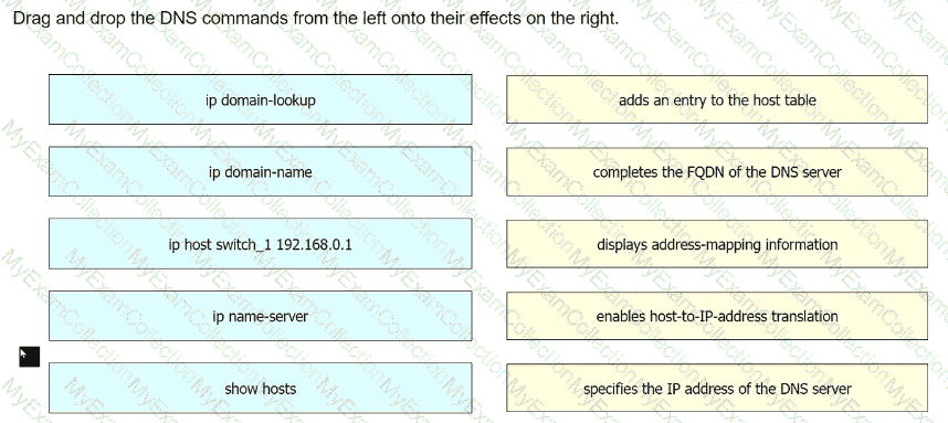
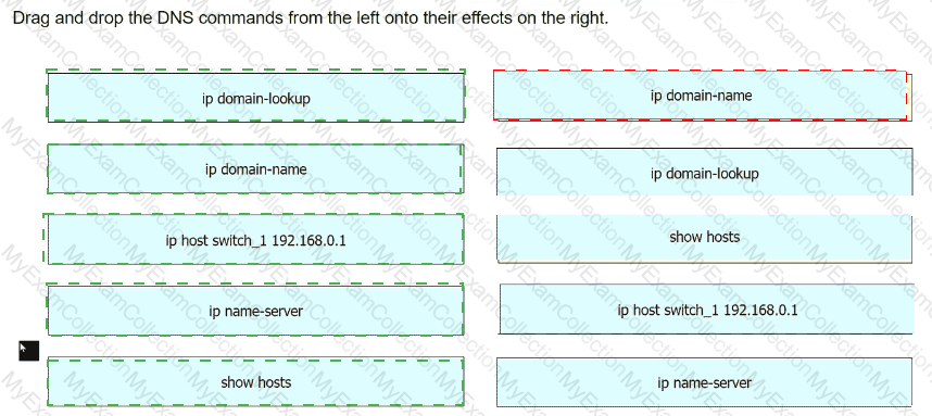
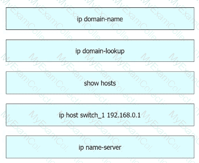
Drag and drop the DNS commands from the left onto their effects on the right.
Question # 306
When an access point is seeking to join wireless LAN controller, which message is sent to the AP- Manager interface?
Question # 307
Refer to the exhibit.
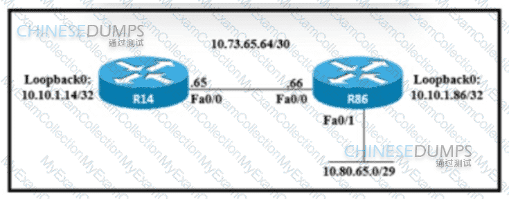
An engineer must configure a floating static route on an external EIGRP network. The destination subnet is the /29 on the LAN Interface of R86. Which command must be executed on R14?
Question # 310
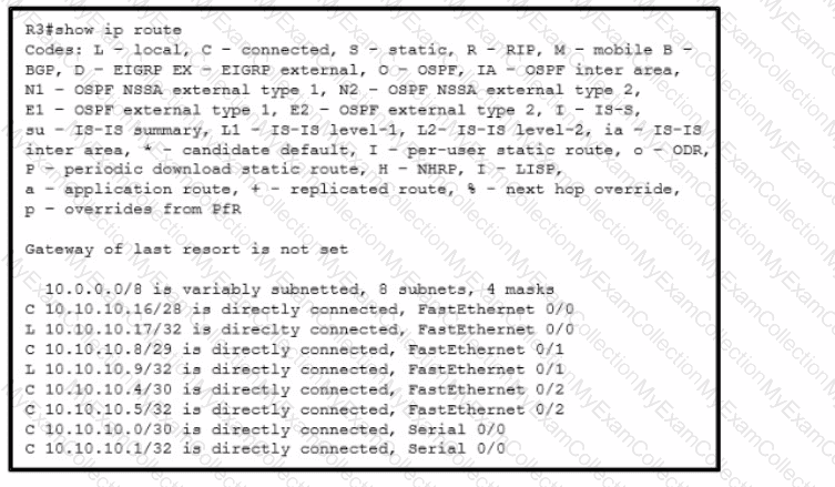
Refer to the exhibit. Which interface does a packet take to reach the destination addresss of 10.10.10.147?