Question # 4
What is the purpose of Bidirectional Forwarding Detection BFD? Choose one.
A.
to process destination host unreachable messages
B.
to detect routing loops
C.
to detect link failures
D.
to detect route flaps
Full Access
Answer:
C
Explanation:
Bidirectional Forwarding Detection is a lightweight, fast failure-detection mechanism used to quickly determine whether a forwarding path between two systems is operational. In Juniper data center networks, BFD is commonly paired with routing protocols such as BGP and OSPF to accelerate convergence. Instead of waiting for a routing protocol hold timer or dead interval to expire, BFD continuously exchanges small control packets between neighbors at a configured interval. If the local device stops receiving these control packets for a negotiated detection time, it declares the BFD session down.
This down event can then be used to immediately signal the routing protocol that the neighbor is no longer reachable, causing faster withdrawal of routes or faster reroute to alternate paths. This is critical in leaf-spine fabrics where rapid failover is expected to maintain application availability and to keep ECMP path sets current. BFD is designed to detect failures in the forwarding plane, including link failures, interface failures, or other failures that prevent packets from being successfully exchanged between the two endpoints. It is not intended to detect routing loops, and it does not specifically track route flaps as a function; flapping is a symptom that may occur when failures happen repeatedly.
Destination host unreachable messages are part of ICMP processing and are unrelated to BFD’s purpose. In short, BFD’s value is fast, protocol-independent failure detection for forwarding adjacency health.
Question # 5
What is the behavior of the default export policy for OSPF?
A.
Accept all routes.
B.
Reject all routes.
C.
Redistribute all routes.
D.
Forward all routes.
Full Access
Answer:
B
Explanation:
In Junos, the default export policy for OSPF is to reject all routes from being exported.
Step-by-Step Breakdown:
Default Export Policy:By default, OSPF in Junos does not export any routes to other routing protocols or neighbors. This is a safety mechanism to prevent unintended route advertisements.
Custom Export Policies:
If you need to export routes, you must create a custom export policy that explicitly defines which routes to advertise.
Example: You can create an export policy to redistribute static or connected routes into OSPF.
Juniper Reference:
OSPF Export Behavior: In Juniper devices, the default policy for OSPF is to reject route advertisements unless explicitly configured otherwise through custom policies.
Question # 6
According to Juniper Networks, the bridge table is more commonly known as a _________.
A.
forwarding table
B.
forwarding bridge
C.
bridging information table
D.
forwarding information table
Full Access
Answer:
A
Explanation:
In Ethernet switching, the bridge table is the data structure that maps MAC addresses to the switch interfaces where those MAC addresses were learned. Juniper commonly describes this function as the Ethernet switching table and also refers to it as the forwarding table in Layer 2 contexts. The concept is the same: the switch learns source MAC addresses from incoming frames, associates them with an ingress port and VLAN or bridge domain, and then uses that learned information to forward future frames to the correct egress port as known unicast.
Calling it a forwarding table is accurate because its primary operational purpose is deciding how to forward Layer 2 frames efficiently. When a destination MAC is present in the table, the switch performs a unicast forward to the learned port. When a destination MAC is not present, the switch treats it as unknown unicast and floods it within the VLAN or bridge domain, while still learning the source MAC for future use.
The term forwarding information table is more strongly associated with Layer 3 routing, where a FIB represents resolved next hops for IP prefixes in the forwarding plane. That is a different structure than the Layer 2 bridge or MAC table. The other options are not standard Juniper terms for this function.
Verification sources from Juniper documentation
https://www.juniper.net/documentation/us/en/software/junos/multicast-l2/topics/topic-map/ethernet-switching-components.html
https://www.juniper.net/documentation/us/en/software/junos/multicast-l2/topics/concept/ethernet-switching-table-understanding.html
Question # 7
What are two characteristics of EBGP? Choose two.
A.
EBGP sessions do not require an IGP.
B.
EBGP sessions require loopback IP address peering.
C.
EBGP does not support sessions with non-directly connected peers.
D.
EBGP sessions are typically established between directly connected peers.
Full Access
Answer:
A, D
Explanation:
EBGP is the BGP session type formed between different autonomous systems. In Juniper data center IP fabrics, EBGP is frequently used for the underlay because it can provide all required reachability without an additional interior gateway protocol. The fabric can advertise loopbacks and point-to-point link subnets directly in BGP, then use ECMP to install multiple equal-cost next hops. This is why EBGP sessions do not require an IGP as a fundamental dependency. Some designs still add an IGP for other reasons, but EBGP itself can carry the underlay routes needed for full fabric connectivity.
EBGP sessions are also typically established between directly connected peers. In a standard leaf-spine underlay, each leaf peers with each spine over the routed physical links between them, using the interface IP addresses on those point-to-point subnets. This matches EBGP default behavior, including a one-hop TTL expectation and straightforward operational troubleshooting.
Loopback peering is not required for EBGP. It is possible, but it usually needs additional configuration such as multihop and a routing method to ensure reachability to the remote loopback before the BGP session can form. EBGP also supports sessions with non-directly connected peers when multihop is configured, so it is incorrect to claim EBGP does not support that capability.
Question # 8
What is a function of an integrated routing and bridging IRB interface?
A.
to route traffic between different VLANs
B.
to encrypt traffic between network segments
C.
to bridge traffic within the same VLAN
D.
to provide Network Address Translation NAT
Full Access
Answer:
A
Explanation:
In Junos-based data center switching, an IRB interface is the Layer 3 gateway that is logically associated with a Layer 2 VLAN or bridge domain. The VLAN provides Layer 2 bridging inside the broadcast domain, while the IRB interface provides the routed interface that enables hosts in that VLAN to reach destinations outside their local subnet. This is the standard mechanism used for inter-VLAN routing on Juniper switches and for providing default gateway services to servers connected to access ports or VLAN-tagged trunks.
Operationally, endpoints in a VLAN use the IRB interface IP address as their default gateway. Frames destined to a remote subnet are bridged at Layer 2 to the IRB gateway MAC address, and then the packet is routed at Layer 3 based on the routing table. This allows a single device to perform both bridging within the VLAN and routing between VLANs or to other routed interfaces, which is why the concept is called integrated routing and bridging.
IRB does not encrypt traffic and does not provide NAT by itself; those functions are typically associated with security services features and firewall platforms. IRB is also not the mechanism that performs pure bridging within the same VLAN, because bridging is handled by the VLAN or bridge domain and the Ethernet switching table.
Question # 9
You are creating an IP fabric underlay and want to use OSPF as your routing protocol.
In this scenario, which statement is correct?
A.
All leaf devices must be configured in separate OSPF areas.
B.
All leaf and spine devices must be the same model to ensure the proper load-balancing behavior.
C.
Interface speeds should be the same throughout the fabric to ensure that all links are utilized.
D.
All spine devices must use the same router ID.
Full Access
Answer:
C
Explanation:
When creating an IP fabric underlay using OSPF as the routing protocol, consistent interface speeds are important to ensure optimal traffic distribution and utilization of all links.
Step-by-Step Breakdown:
OSPF and Interface Speeds:OSPF calculates the cost of a link based on its bandwidth. The default cost calculation in OSPF is:

If interface speeds vary significantly, OSPF may choose paths with lower cost (higher bandwidth), resulting in some links being underutilized.
Equal Utilization:To ensure that all links are equally utilized in an IP fabric, it is recommended to maintain uniform interface speeds across the fabric. This ensures balanced load sharing across all available paths.
Juniper Reference:
IP Fabric with OSPF: Juniper recommends consistent interface speeds to maintain even traffic distribution and optimal link utilization in IP fabric underlay designs.
Question # 10
Which statement about the qualified next-hop feature is correct when configuring a static route?
A.
Qualified next-hop is used for specifying redundant next-hops.
B.
Qualified next-hop is used when the next-hop address is not within the route table of the local device.
C.
Qualified next-hop is only required when a link-state protocol is configured.
D.
Qualified next-hop uses pings to verify that the next hop is up.
Full Access
Answer:
A
Explanation:
Qualified next hop is the Junos mechanism that lets you configure more than one next hop for the same static route and control which one is preferred. This is most commonly used to build primary and backup forwarding behavior with deterministic selection. You configure a primary next hop and then add one or more qualified next hops with a different preference value. The route installs the best, lowest preference next hop as active, while keeping the alternate next hop available as standby. If the primary next hop becomes unusable, Junos can switch to the qualified next hop so traffic continues to flow.
This approach is widely used in data center edge and services routing, for example toward management networks, service appliances, or external gateways where you want a static default or summary route with predictable failover. It is not the same as resolving a non-directly-connected next hop. That scenario is handled by recursive resolution behavior, not by qualification. Qualified next hop also does not depend on any specific routing protocol, and it is not limited to link-state environments.
Finally, qualified next hop does not rely on sending pings to test reachability. Health tracking can be achieved through other mechanisms such as interface state, next hop resolution changes, or integration with failure detection features, but the qualified next hop feature itself is about preference-ranked redundancy for static routes.
Question # 11
How does a Layer 2 switch create an Ethernet switching table? Choose one.
A.
It records the source MAC address of the received frames.
B.
It downloads the table from the root bridge of the STP domain.
C.
It uses a Layer 2 firewall filter.
D.
It records the destination MAC address of the received frames.
Full Access
Answer:
A
Explanation:
A Layer 2 switch builds its Ethernet switching table through a learning process based on the source MAC addresses of incoming frames. When a frame arrives on an interface within a VLAN or bridge domain, the switch examines the source MAC address and associates it with the ingress interface and VLAN context. If the MAC address is new, the switch creates a new entry; if it already exists but is seen on a different interface, the switch updates the entry to reflect the new location. This dynamic learning is fundamental to efficient unicast forwarding and is why option A is correct.
Once the switch has learned MAC-to-port mappings, it can forward subsequent frames destined to those MAC addresses as known unicast out the specific egress interface rather than flooding them. If the destination MAC is unknown, the switch typically floods the frame within the VLAN or bridge domain to discover the correct destination. When the destination replies, the switch learns that MAC as a source, completing the learning cycle.
Spanning Tree Protocol does not provide a MAC table and there is no concept of downloading an Ethernet switching table from a root bridge. STP’s role is loop prevention and topology control at Layer 2, not MAC learning distribution. Firewall filters can enforce policy but do not create the switching table. Recording destination MAC addresses would not correctly learn endpoint locations because the destination can be unknown when the first frames are sent; source learning is reliable because every received frame carries the sender’s MAC address.
Question # 12
Which feature should be used with a static route that has a secondary next hop with a unique route preference value? Choose one.
A.
retain
B.
resolve
C.
qualified next hop
D.
install
Full Access
Answer:
C
Explanation:
In Junos, a static route can be configured with multiple next hops. When you want a “primary and backup†behavior, the correct mechanism is a qualified next hop. A qualified next hop allows you to assign a different preference to each next hop for the same destination prefix. The static route with the best preference is selected as active, while the higher-preference value next hop remains available as a standby option. If the primary next hop becomes unusable, Junos can install the backup qualified next hop so forwarding continues with minimal operational change, which is a common requirement for data center edge or services routing where predictable failover is needed.
The key point in the question is “secondary next hop with a unique route preference value.†That wording maps directly to qualified next-hop behavior, because qualification is how Junos differentiates multiple next hops under the same route using distinct preference values. The retain option relates to keeping routes in the routing table under certain conditions and does not specifically create primary/backup next-hop selection based on preference. The resolve option concerns how the system resolves a next hop through another route and is not the feature that creates a preference-ranked secondary next hop. The install option is not the mechanism used to define backup next-hop preference for a static route.
Question # 13

Referring to the exhibit, what does the configuration do?
A.
It only disables graceful restart for the BGP protocol.
B.
It disables graceful restart globally for all protocols.
C.
It only disables graceful restart for defined static routes.
D.
It disables graceful restart for all routes defined under the routing-options hierarchy.
Full Access
Answer:
B
Explanation:
The configuration is applied under the routing-options hierarchy and specifically under graceful-restart with the statement disable. In Junos, routing-options graceful-restart is the global control point used to enable or manage graceful restart behavior at the system routing level. When graceful restart is enabled, the router can continue forwarding and temporarily suppress certain routing protocol update behavior during a routing process restart or control-plane event, allowing the network to avoid unnecessary reconvergence and route churn.
Placing disable under routing-options graceful-restart turns off graceful restart globally. This means the device will not attempt to use graceful restart mechanisms for routing protocols at the global level. Protocol-specific graceful restart configuration exists under each routing protocol hierarchy, but the exhibit shows the global routing-options location, which impacts overall graceful restart behavior for the routing subsystem.
Option A is incorrect because disabling BGP graceful restart only would be done under the BGP protocol hierarchy, not routing-options. Option C is incorrect because graceful restart is a routing protocol restart behavior, not something applied only to static routes. Option D is also incorrect because the setting is not scoped to specific route statements under routing-options; it disables the graceful restart feature itself, not individual routes.
In data center environments, globally disabling graceful restart may be chosen when an operator prefers deterministic, immediate reconvergence behavior or when interoperability testing indicates graceful restart helper or restart behavior is undesired with specific peers.
Question # 14
Which two statements are correct about configuring VLANs? Choose two.
A.
You must assign an IRB interface to each VLAN.
B.
You must assign a VLAN name or ID and a Layer 2 interface to the VLAN.
C.
You can assign one or more VLANs to a trunk mode interface.
D.
You can assign one or more VLANs to an access mode interface.
Full Access
Answer:
B, C
Explanation:
On Junos switching platforms used in data centers, a VLAN is a Layer 2 broadcast domain. To make a VLAN functional for user traffic, you define the VLAN with a name and typically a VLAN ID, and you associate Layer 2 interfaces with that VLAN so frames arriving on those interfaces are placed into the correct broadcast domain. Without interface membership, the VLAN exists as configuration but does not carry endpoint traffic because no ports participate in it. This is why assigning a VLAN name or ID and associating Layer 2 interfaces to the VLAN is a correct requirement.
Trunk mode interfaces are designed to carry multiple VLANs over a single physical link using 802.1Q tagging. In a data center, trunks are common on leaf-to-spine uplinks, switch-to-switch connections, and server connections where the host or hypervisor tags multiple VLANs. Therefore, assigning one or more VLANs to a trunk port is correct.
An IRB interface is not required for every VLAN. IRB is only needed when the VLAN requires Layer 3 gateway functionality, such as inter-VLAN routing or default gateway services for that subnet. Pure Layer 2 VLANs do not need IRB. Also, an access mode interface is intended to belong to a single VLAN and typically carries untagged traffic, so assigning multiple VLANs to an access mode interface is not correct in standard Ethernet switching behavior.
Question # 15
You have a problem bringing up an aggregated Ethernet interface between a spine and a leaf.
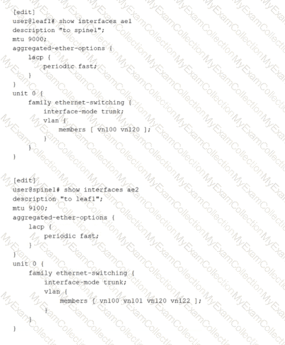
Referring to the exhibit, what is the problem?
A.
The active statement must be added to LACP under the aggregated-ether-options hierarchy on one or both sides.
B.
The ae interface numbers are not consistent.
C.
The leaf-and-spine VLAN memberships are not consistent and should be changed to include the additional VLANs defined on spine1.
D.
The leaf-and-spine MTUs are not consistent.
Full Access
Answer:
A
Explanation:
An aggregated Ethernet interface that uses LACP requires at least one side to actively initiate LACP negotiations. In the exhibit, both devices have LACP configured only with periodic fast, but neither side explicitly enables LACP active mode. When both ends operate in passive behavior, each side waits for the other to send LACP Data Units, and no negotiation begins. As a result, the LACP state does not progress to collecting and distributing, and the aggregated link fails to form as expected. Adding the active statement under the LACP hierarchy on one or both ends ensures that LACP frames are transmitted and the bundle can be negotiated and brought up.
The other options are not the root cause for bringing the bundle up. The aggregated Ethernet interface number does not need to match across devices because the bundle is locally significant on each system. VLAN membership differences on a trunk do not prevent LACP from establishing the aggregate; they only affect which tagged VLANs are allowed to pass once the link is operational. MTU differences can cause data plane issues such as fragmentation or drops for jumbo frames, but they do not typically prevent LACP formation because control frames are small and the physical link can still come up.
Question # 16
Referring to the exhibit,
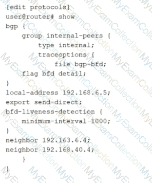
how much time must pass before a neighbor is considered down?
A.
5000 ms
B.
2000 ms
C.
1000 ms
D.
3000 ms
Full Access
Answer:
D
Explanation:
The exhibit shows BFD liveness detection configured under a BGP group with minimum-interval set to 1000 milliseconds. In Junos, BFD provides rapid failure detection by sending periodic BFD control packets between neighbors. The minimum-interval value is the negotiated minimum transmit and receive interval used for BFD control packets for that session. A neighbor is declared down when the local system fails to receive a certain number of consecutive BFD packets within the expected time window.
That time window is determined by the BFD detection time, which is calculated as the minimum-interval multiplied by the BFD multiplier. The multiplier represents how many BFD control packets can be missed before the session is considered failed. If the multiplier is not explicitly configured, Junos uses the default multiplier value of 3. Therefore, with minimum-interval set to 1000 ms and the default multiplier of 3, the detection time becomes 3000 ms. After approximately 3 seconds without receiving the expected BFD control packets, the BFD session transitions to down and BGP can react by treating the associated peer as unreachable for fast convergence.
This behavior is commonly used in data center underlays and EVPN fabrics to reduce convergence time compared to relying only on BGP hold timers.
Question # 17
Which state in the adjacency process do OSPF routers check the MTU size?
A.
Init
B.
Exchange
C.
Done
D.
ExStart
Full Access
Answer:
B
Explanation:
In OSPF, routers exchange link-state information in different stages to establish full adjacency. The MTU size is checked during the Exchange state.
Step-by-Step Breakdown:
1.    OSPF Adjacency Process:
o  OSPF routers go through multiple stages when forming an adjacency: Down, Init, 2-Way, ExStart, Exchange, Loading, and Full.
2.    Exchange State:
o  During the Exchange state, OSPF routers exchange Database Description (DBD) packets to describe their link-state databases. The MTU size is checked at this stage to ensure both routers can successfully exchange these packets without fragmentation.
o  If there is an MTU mismatch, the routers may fail to proceed past the Exchange state.
Juniper Reference:
·       MTU Checking in OSPF: Junos uses the Exchange state to check for MTU mismatches, ensuring that routers can properly exchange database information without packet fragmentation issues.
Question # 18
When evaluating BGP routes, what will be evaluated first?
A.
The local preference value
B.
The AS path
C.
The MED value
D.
The origin value
Full Access
Answer:
A
Explanation:
In BGP (Border Gateway Protocol), when evaluating multiple routes to the same destination, the first attribute that is considered is the local preference value. The local preference is a BGP attribute used to influence outbound routing decisions within an Autonomous System (AS).
Step-by-Step Breakdown:
Local Preference:The local preference attribute is used to determine which path is preferred for traffic leaving the AS. The higher the local preference value, the more preferred the route.
BGP Path Selection:The BGP path selection process evaluates the following attributes in this order:
Local Preference (higher is preferred)
AS Path (shorter is preferred)
Origin (IGP > EGP > incomplete)
MED (Multi-Exit Discriminator) (lower is preferred)
Juniper Reference:
BGP Path Selection: In Junos, the local preference attribute is the first to be evaluated when determining the best path for outbound traffic.
Question # 19
What are two names used to refer to the Layer 2 table that maintains known switching information? Choose two.
A.
inet.0 table
B.
routing information base RIB
C.
Ethernet switching table
D.
forwarding information base FIB
Full Access
Answer:
C, D
Explanation:
On Junos Ethernet switching platforms, the Layer 2 forwarding decision is based on a MAC address lookup table. Juniper commonly refers to this as the Ethernet switching table, which contains learned source MAC addresses mapped to an ingress interface and a VLAN or bridge domain context. This table is built dynamically through normal Layer 2 learning, and it is what allows the switch to forward known unicast frames to the correct egress interface instead of flooding within the broadcast domain.
In Juniper terminology, the forwarding plane also maintains a forwarding database used to program hardware forwarding entries. While the term forwarding information base is most often associated with Layer 3 forwarding for IP prefixes, many training and operational contexts use FIB language when describing the programmed forwarding state in the data plane, including the entries that result from Ethernet switching learning. The key idea is that the control plane and switching processes populate forwarding state, and the forwarding plane uses that state to make fast, deterministic forwarding decisions at line rate.
Options inet.0 and RIB are Layer 3 constructs. inet.0 is the main IPv4 routing table, and the RIB is the routing information base that stores routes before they are programmed into forwarding. Neither represents the Layer 2 MAC learning table.
Question # 20
You want to enable routing between VLAN 10 and VLAN 20.
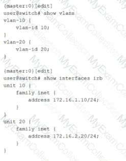
Which two configuration statements must be included in the configuration shown in the exhibit to accomplish this task? Choose two.
A.
set vlans default vlan-id 20
B.
set vlans vlan-10 l3-interface irb.10
C.
set vlans vlan-20 l3-interface irb.20
D.
set vlans default vlan-id 10
Full Access
Answer:
B, C
Explanation:
Inter-VLAN routing on Junos switching platforms is typically implemented by associating each VLAN or bridge domain with an IRB interface that provides the Layer 3 gateway for that VLAN. In the exhibit, VLAN 10 and VLAN 20 are defined with vlan-id values, and IRB logical units 10 and 20 already have IPv4 addresses assigned. However, the VLAN definitions do not yet reference the IRB interfaces. Without that association, hosts in the VLANs have no routed gateway on the switch, and the switch cannot perform Layer 3 forwarding between the two VLAN subnets.
To enable routing, each VLAN must include an l3-interface statement that binds the VLAN to the corresponding IRB logical unit. Adding l3-interface irb.10 under vlan-10 makes irb.10 the default gateway interface for VLAN 10 and enables the device to route traffic sourced from that VLAN. Adding l3-interface irb.20 under vlan-20 does the same for VLAN 20. Once both VLANs are bound to their IRB interfaces, the switch can route packets between 172.16.1.0/24 and 172.16.2.0/24 using its routing table, while still switching Layer 2 traffic within each VLAN.
The default VLAN settings are unrelated to enabling routing between these two specific VLANs. They control the behavior of the default VLAN, not the creation of Layer 3 gateways for VLAN 10 and VLAN 20.