Question # 4
What operating system supports the last crash tool in iDRAC?
A.
MS Windows
B.
ESXi
C.
SUSE Linux
D.
Unix
Full Access
Answer:
C
Explanation:
Understanding the Last Crash Tool in iDRAC
Server Troubleshooting (32%)
Explain Configuration Validation, crash capture, and minimum to POST
What is the Last Crash Tool in iDRAC?
Last Crash Screen: A feature in iDRAC that captures the last crash screen output from the operating system before a system crash or unexpected reboot.
Purpose: Provides valuable information for diagnosing the cause of a system crash, aiding in troubleshooting efforts.
Operating System Support
The Last Crash Screen feature is dependent on the operating system's ability to output crash information to the VGA console, which iDRAC can then capture.
Explanation of Options
Option A: MS Windows
Explanation: While Windows systems do produce crash screens (Blue Screen of Death), capturing this screen via iDRAC requires specific configurations and may not be fully supported.
Conclusion: Less likely to be the correct answer.
Option B: ESXi
Explanation: VMware ESXi can produce Purple Screen of Death (PSOD), but capturing this via iDRAC's Last Crash Screen feature is not typically supported without additional configuration.
Conclusion: Less likely to be the correct answer.
Option C: SUSE Linux
Explanation: SUSE Linux supports kernel crash dumps and can output crash information to the console, which iDRAC can capture using the Last Crash Screen feature.
Conclusion: Correct Answer.
Option D: Unix
Explanation: "Unix" is a broad term encompassing various operating systems. Without specifying, it's unclear which Unix variant is being referred to, and support may vary.
Conclusion: Less specific; not the best answer.
Dell Operate References
Server Troubleshooting (32%)
Explain Configuration Validation, crash capture, and minimum to POST: Emphasizes the importance of understanding features like the Last Crash Screen for troubleshooting.
System Administration (18%)
Verify health status and iDRAC license: Ensuring that the necessary features are enabled and supported on the operating system in use.
Conclusion
SUSE Linux supports the Last Crash Screen tool in iDRAC, allowing for the capture and analysis of crash information directly from the server's console output.
Question # 5
What are the two purposes of E3 EDSFF drives?
(Select 2)
A.
Provides higher interface speed with PCIe Gen4.
B.
Replaces 3.5" and M.2 form factors.
C.
Provides a common form factor for accelerator and computational storage.
D.
Replaces 2.5" and U.2 form factors.
Full Access
Answer:
C, D
Explanation:
Understanding E3 EDSFF Drives
Server Components (26%)
Define storage options, Drives
What is EDSFF?
Enterprise and Datacenter Storage Form Factor (EDSFF) is a family of SSD form factors designed for enterprise and data center applications.
E3 Form Factor: A specific size within the EDSFF standard, optimized for performance, density, and thermal efficiency.
Purposes of E3 EDSFF Drives
Replaces 2.5" and U.2 Form Factors
Explanation:
E3 drives are intended to replace traditional 2.5" SSDs and U.2 form factors.
They offer higher density, improved thermal characteristics, and better scalability.
Conclusion: Option D is Correct
Provides a Common Form Factor for Accelerator and Computational Storage
Explanation:
E3 EDSFF drives are designed to support not only storage but also accelerator devices like GPUs, FPGAs, and computational storage.
This standardization simplifies system design and improves compatibility.
Conclusion: Option C is Correct
Explanation of Options
Option A: Provides higher interface speed with PCIe Gen4
Analysis: While EDSFF drives do support PCIe Gen4, their primary purpose is form factor standardization and scalability, not just providing higher interface speeds.
Conclusion: Not the main purpose.
Option B: Replaces 3.5" and M.2 form factors
Analysis: E3 EDSFF does not directly replace 3.5" HDDs or M.2 SSDs, which serve different purposes and sizes.
Conclusion: Incorrect.
Option C: Provides a common form factor for accelerator and computational storage
Analysis: Correct as per the explanation above.
Conclusion: Correct Answer
Option D: Replaces 2.5" and U.2 form factors
Analysis: Correct as per the explanation above.
Conclusion: Correct Answer
Dell Operate References
Server Components (26%)
Define storage options, Drives: Knowledge of new storage technologies and form factors is essential for modern server configurations.
Server Portfolio and Features (10%)
Identify server features and specifications: Understanding hardware advancements and their practical benefits.
Conclusion
The E3 EDSFF drives serve to replace traditional 2.5" and U.2 form factors (Option D) and provide a common form factor for accelerator and computational storage devices (Option C), enhancing scalability and compatibility in data centers.
Question # 6
Which two models are 16th generation PowerEdge rack servers? (Select 2)
A.
R650
B.
MX760C
C.
R760
D.
C6620
E.
XE9680
Full Access
Answer:
C, E
Explanation:
Identifying 16th Generation PowerEdge Rack Servers
Server Portfolio and Features (10%)
Define chassis form factors and numbering nomenclature
Identify server features and specifications
Position the server in the market landscape
Understanding Dell PowerEdge Server Generations and Models
Dell PowerEdge servers are categorized by generation (denoted as "G") and model numbers. The 16th Generation (16G) represents the latest series of Dell servers as of 2023, featuring the newest technologies and enhancements.
Evaluation of Options:
Option A: R650
Explanation: The PowerEdge R650 is a 15th Generation (15G) server.
Conclusion: Not a 16G server.
Option B: MX760C
Explanation: The PowerEdge MX760c is a compute sled for the Dell PowerEdge MX7000 modular chassis.
Generation: It is part of the 16th Generation, but it is a modular blade server, not a rack server.
Conclusion: Since the question asks for rack servers, this may not be the best fit.
Option C: R760
Explanation: The PowerEdge R760 is a 16th Generation rack server.
Features:
2U rack form factor
Supports latest Intel Xeon Scalable processors
Enhanced performance and scalability
Conclusion: Correct Answer.
Option D: C6620
Explanation: The PowerEdge C6620 is a 15th Generation server designed for high-density compute environments.
Conclusion: Not a 16G server.
Option E: XE9680
Explanation: The PowerEdge XE9680 is a 16th Generation rack server designed for extreme performance, particularly for AI and HPC workloads.
Features:
Supports up to eight GPUs
High-performance computing capabilities
Conclusion: Correct Answer.
Additional Notes:
Rack Servers vs. Modular Servers:
Rack Servers: Standalone servers that mount directly into standard server racks (e.g., R-series, XE-series).
Modular Servers: Compute modules that fit into a shared chassis (e.g., MX-series). While they can be mounted in racks, they are not considered standalone rack servers.
Dell Operate References:
Server Portfolio and Features (10%)
Define chassis form factors and numbering nomenclature: Understanding model numbers helps identify the server generation.
Identify server features and specifications: Recognizing the characteristics of 16G servers.
Position the server in the market landscape: Knowing which servers are current and their intended workloads.
Conclusion:
The PowerEdge R760 and XE9680 are both 16th Generation rack servers. They represent the latest in Dell's server technology and are designed to meet modern data center needs.
Question # 7
Due to recent security breaches and to avoid accidental changes made by the junior IT staff, an
administrator would like to prevent unwanted configuration changes in the iDRAC UI.

Full Access
Answer:
Answer:
See the Explanation for Step by Step solution.
Explanation:
To prevent unwanted configuration changes in the iDRAC UI, you can adjust user roles, permissions, or enable specific security settings to restrict access for junior IT staff. Here are the steps to secure the iDRAC configuration:
Step-by-Step Guide:
Access User Settings:
In the iDRAC interface, navigate to iDRAC Settings from the main menu.
Choose User Authentication or Users to manage user accounts and permissions.
Adjust User Roles and Permissions:
Identify the accounts associated with junior IT staff.
For each user account, adjust the role to Read-Only if you want them to have view-only access without making configuration changes.
Alternatively, set their permissions to exclude configuration changes. This may involve assigning a custom role with limited access based on your needs.
Enable Configuration Lock (if available):
Some versions of iDRAC offer a Configuration Lock feature, which prevents any configuration changes until the lock is removed by an administrator.
Navigate to Configuration > System Security or User Authentication, depending on the version, and enable the Configuration Lock option.
Set Up Two-Factor Authentication (Optional):
For added security, enable Two-Factor Authentication under iDRAC Settings > Network or Security settings. This step ensures only authorized users can access and make changes to the iDRAC UI.
Save and Apply Security Changes:
After setting up the desired restrictions and permissions, save the settings to apply the changes.
Verify that junior IT staff accounts now have restricted access and cannot make configuration changes.
Log Out and Test the Changes:
Log out of the administrator account and log in with a junior IT staff account to confirm that the permissions are set correctly.
Ensure that configuration changes are disabled and that the user can only view the iDRAC interface as per the restrictions.
By following these steps, you can restrict junior IT staff from making any configuration changes within the iDRAC interface, thus preventing accidental or unauthorized modifications.
Question # 8
Click the Launch Simulator button.
Using the iDRAC UI, what is listed as the Cache Memory Size for the H965i storage controller?
Note: It is necessary to close (x) the simulator window before you can select a response to this question.
A.
965 MB
B.
8361 MB
C.
1064 MB
D.
8 GB
Full Access
Answer:
D
Explanation:
ï‚· Launch the Simulator:
Open the PowerEdge iDRAC simulator to access the user interface and perform the required task.
ï‚· Navigate to System Information:
In the top menu bar, select the "Configuration" tab.
From the options that appear, choose "Storage". This section will display details and configurations for the storage controllers installed on the server.
ï‚· Check the H965i Storage Controller:
Locate the H965i storage controller in the list. Selecting it should bring up a summary page with various specifications for the controller.
Look for the field labeled "Cache Memory Size". This will provide the cache memory size value for the controller.
Question # 9
An administrator has been tasked to create and save replacement of a server configuration with the file
name of "PE-server".
The profile must include the configuration for only the following components:
. NIC
. RAID
. iDRAC
Using the simulator, create and save the replacement with these components.
Full Access
Answer:
Answer:
See the Explanation for Step by Step solution.
Explanation:
To create and save a server configuration profile with specific components in the iDRAC interface, follow these steps:
Step-by-Step Guide:
Access Configuration Profiles:
Go to the "Configuration" tab on the top menu bar.
From the dropdown options, select "Server Configuration Profile."
Create a New Profile:
Within the Server Configuration Profile section, choose the option to Create a New Profile.
You will likely see options to specify which components to include in the configuration profile.
Select Components:
When prompted, select only the components required for the configuration:
NIC: Network Interface Card settings.
RAID: Storage controller and RAID configuration.
iDRAC: iDRAC management settings.
Ensure that other components are not selected to meet the requirement.
Save the Configuration:
Enter the file name "PE-server" for the profile.
Choose the option to Save or Export the configuration profile. This should save the configuration to the specified name, typically on the server or local storage available through iDRAC.
Verify the Profile Creation:
After saving, verify that the profile appears in the list of server configuration profiles with the name "PE-server."
Confirm that it includes only the selected components.
By following these steps, you should successfully create and save the configuration profile with the specified components.
Question # 10
Using the iDRAC UI, generate and save locally a SupportAssist collection with system
information and debug logs only.

Full Access
Answer:
Answer:
See the Explanation for Step by Step solution.
Explanation:
To generate and save a SupportAssist collection with system information and debug logs only in the iDRAC UI, follow these steps:
Step-by-Step Guide:
Access SupportAssist in iDRAC:
In the iDRAC interface, navigate to the Maintenance tab in the top menu.
From the dropdown, select SupportAssist. This will bring up the SupportAssist options.
Initiate a Collection:
In the SupportAssist section, look for the option to Create a New Collection or Start a Collection.
Choose Collect System Data or Generate a Collection, depending on the version of iDRAC.
Select Collection Components:
When prompted to select components for the collection, check the boxes for System Information and Debug Logs only.
Ensure no other components are selected to limit the collection to just the required data.
Start the Collection:
Confirm your selection, then click Start or Generate. This will initiate the process to gather the specified data from the system.
Save the Collection Locally:
Once the collection is complete, you should see an option to Download or Save the file.
Click the download link and save the collection file locally on your computer.
Verify the Collection File:
Check the downloaded file to ensure it contains only the system information and debug logs. It should be in a format such as ZIP or TAR, depending on the system configuration.
By following these steps, you can successfully generate a SupportAssist collection with just the system information and debug logs and save it to your local system for further review or support purposes.
Question # 11
A system administrator is asked to create an iDRAC shared management port using LOM2 and
create a failover network using LOM3. Use the simulator to accomplish this task.
Full Access
Answer:
Answer:
See the Explanation for Step by Step solution.
Explanation:
To configure an iDRAC shared management port with LOM2 and set up a failover network using LOM3 in the iDRAC interface, follow these steps:
Step-by-Step Guide:
Access iDRAC Network Settings:
In the iDRAC interface, navigate to the iDRAC Settings tab in the top menu bar.
Select Network from the dropdown options to access network configuration settings.
Configure the Shared Management Port:
In the Network settings, locate the section for Network Interface or LAN Interface Configuration.
Change the NIC Selection to Shared. This will enable the use of a LAN on Motherboard (LOM) port for iDRAC management.
Select LOM2 for the Shared Management Port:
Once you’ve selected Shared, additional options should appear for selecting the specific port.
Choose LOM2 as the Shared Management Port. This configures iDRAC to use LOM2 for its primary network connection.
Enable Failover and Select LOM3:
Look for the Failover settings within the same Network Interface configuration.
Enable Failover and select LOM3 as the failover network port. This configuration allows iDRAC to switch to LOM3 automatically if there is an issue with the connection on LOM2.
Save and Apply Settings:
Once you have configured the shared management port and failover settings, click Apply or Save to confirm the configuration.
The iDRAC interface may briefly refresh, and you should receive a confirmation that the settings have been applied successfully.
Verify Configuration:
After the settings are saved, you can verify that LOM2 is listed as the shared management port and that LOM3 is set as the failover port under Network settings.
By following these steps in the simulator, you should be able to configure iDRAC to use LOM2 for the shared management port and set up a failover network with LOM3. Make sure to save your changes to apply the configuration.
Question # 12
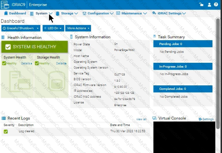
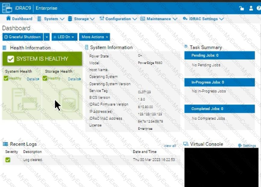
The system administrator receives an email notification on April 30, 2022 that a power issue was reported on the Dell PowerEdge R660. Which log entry helps them investigate this issue for that date?

A.
Under voltage fault detection on power supply 1.
B.
Power supply 2 has failed.
C.
Under voltage fault detected on power supply 2.
D.
Power supply 1 has failed.
Full Access
Answer:
C
Explanation:
To investigate a power issue on a specific date, such as April 30, 2022, the system administrator should examine the iDRAC logs for entries related to power supply faults or failures. Here's how to approach finding the correct answer:
Step-by-Step Approach:
Access the System Logs:
In the iDRAC interface, navigate to the Dashboard tab.
Scroll down to the Recent Logs section or navigate to System Logs under Maintenance or iDRAC Settings (depending on the iDRAC version) to access detailed logs.
Filter Logs by Date:
Use the filter option to specify the date, focusing on entries from April 30, 2022. This will help narrow down relevant events.
Identify Power-Related Entries:
Look for log entries that mention power supply issues or voltage faults around the specified date. In this case, entries related to under-voltage faults or power supply failures will be critical.
Interpret the Log Entries:
Based on typical power fault logs, consider the possible answers:
A. Under voltage fault detection on power supply 1: Indicates a voltage issue was detected on PSU1.
B. Power supply 2 has failed: Indicates PSU2 has completely failed.
C. Under voltage fault detected on power supply 2: Indicates a voltage issue was detected on PSU2.
D. Power supply 1 has failed: Indicates PSU1 has completely failed.
The specific log entry depends on the exact wording in the logs. However, from the options provided, if the administrator received a notification about a power issue, the most likely scenario involves a failure or under-voltage detection.
Question # 13
The system administrator cannot boot their R660 server. To help troubleshooting, use the iDRAC
Ul to enable capturing the full POST sequence for the next time it attempts to boot.
 Answer: See the Explanation for Step by Step solution.
Full Access
Answer:
Explanation:
To enable capturing the full POST (Power-On Self-Test) sequence using the iDRAC interface, follow these steps:
Step-by-Step Guide:
Log into the iDRAC Interface:
Access the iDRAC UI using the server’s IP address from a web browser.
Enter your credentials to log in.
Navigate to System BIOS Settings:
Go to the Configuration tab on the top menu.
Select BIOS Settings from the dropdown menu. This will take you to the settings where you can manage BIOS-related configurations.
Enable POST Sequence Logging:
In the BIOS Settings, look for an option related to POST Behavior or Boot Sequence Capture.
Enable Verbose Mode or Capture Full POST Sequence. This setting ensures that the entire POST process is logged in detail during the next boot attempt.
Alternatively, if there is a specific setting for Capture System Boot Logs, enable it to ensure detailed logging during POST.
Apply the Changes:
After enabling the POST capture option, click Apply or Save.
iDRAC may prompt for confirmation or inform you that changes will take effect upon the next reboot. Confirm any prompts as required.
Restart the Server (if necessary):
If the server is currently off, attempt to power it on. If it’s on, you may need to perform a Graceful Shutdown followed by a restart to initiate the POST sequence.
Review POST Logs After Reboot:
Once the server attempts to boot, return to the iDRAC Logs section to review the captured POST logs.
Go to Maintenance > System Event Log or Lifecycle Log to view the detailed logs from the POST sequence. This can help diagnose why the server is failing to boot.
By enabling this setting, you will capture detailed information during the POST process, which can then be reviewed to identify any hardware or configuration issues preventing the server from booting successfully.
Question # 14
A customer wants to change the PSU configuration to a 2+0 with PSU2 as the primary. Use the simulator to complete this task in the iDRAC UI.

Full Access
Answer:
Answer:
See the Explanation for Step by Step solution.
Explanation:
To change the Power Supply Unit (PSU) configuration to a 2+0 setup with PSU2 as the primary in the iDRAC interface, follow these steps:
Step-by-Step Guide:
Navigate to Power Management Settings:
In the iDRAC interface, go to the Configuration tab at the top.
Select Power Management from the dropdown options.
Locate the Power Configuration Section:
Within the Power Management settings, look for a section labeled Power Configuration or Power Supply Configuration.
Select the Redundancy Policy:
Change the Redundancy Policy to 2+0. In this configuration, there will be no redundancy, and both power supplies will be active but configured as independent power sources without failover.
Set PSU2 as the Primary PSU:
Locate the option to designate the Primary PSU. Select PSU2 as the primary power source.
This setting ensures that PSU2 will handle the primary power load under normal conditions.
Apply and Save Changes:
Once you have made these changes, click Apply or Save to confirm the new configuration.
The interface may prompt for confirmation, after which the settings will be saved, and PSU2 will become the primary power supply under a 2+0 configuration.
Verify Configuration:
Review the updated settings to confirm that PSU2 is now set as primary and that the redundancy policy is 2+0, meaning only PSU2 is actively providing power without a secondary backup.
By following these steps in the iDRAC simulator, you will set up PSU2 as the primary power source with no redundancy, ensuring a 2+0 configuration. This setup will leverage PSU2 exclusively without automatic failover to another power supply.
Question # 15
How does the host iDRAC communicate when using the Group Manager feature?
A.
IPv6
B.
Telnet
C.
SSH
D.
Redfish
Full Access
Answer:
D
Explanation:
Understanding iDRAC Group Manager Communication
Server Management and Configuration Tools (14%)
Explain the management interface options - LCC, racadm, OMSA, iSM, OME
What is iDRAC Group Manager?
iDRAC Group Manager allows administrators to manage multiple iDRAC-enabled servers as a single group.
Purpose: Simplifies management tasks by enabling actions to be performed across multiple servers simultaneously.
Communication Protocol Used
Redfish Protocol
Explanation: Redfish is a modern, RESTful API designed for server management.
Usage in iDRAC Group Manager: iDRAC instances communicate with each other using the Redfish protocol to share information and coordinate management actions.
Benefits:
Secure communication over HTTPS.
Supports JSON data format, making it easy to integrate with web services.
Designed for scalability and interoperability.
Explanation of Options
Option A: IPv6
Explanation: IPv6 is an IP addressing protocol, not a communication method or protocol used by iDRAC for Group Manager features.
Conclusion: Incorrect.
Option B: Telnet
Explanation: Telnet is an unencrypted, insecure protocol for command-line access; it is not used for iDRAC Group Manager communication.
Conclusion: Incorrect.
Option C: SSH
Explanation: SSH provides secure command-line access but is not the protocol used for iDRAC instances to communicate within the Group Manager.
Conclusion: Incorrect.
Option D: Redfish
Correct Answer: iDRAC uses the Redfish protocol for communication when utilizing the Group Manager feature.
Dell Operate References
Server Management and Configuration Tools (14%)
Emphasizes understanding management interfaces and protocols.
Explain the management interface options - LCC, racadm, OMSA, iSM, OME
Includes knowledge of modern protocols like Redfish used in server management.
Conclusion
When using the Group Manager feature, iDRAC instances communicate with each other using the Redfish protocol, enabling secure and efficient management of server groups.